
Instruction Manual


3-24 F-620-0912 Edition
ASSEMBLY INSTRUCTIONS
Final Assembly
1. Attach a tractor to the implement and charge the lift
system hydraulics as described in “Hydraulic Lift
System” on page 4-3.
2. Install the 1-1/2 x 16 lockouts on both 3-1/2 x 16
cylinders on the frame.
3. Connect lights to the tractor and verify operation.
4. Check tires for proper inflation
5. Level the Weatherproofer I from front to rear as
described in “Leveling (Front-to-Rear)” on
page 4-4.
6. Inspect the final implement assembly, and verify that
all bolts have been tightened, cotter pins spread, and
that there are no leaking hydraulic connections.
CAUTION
7. Rotate each disc gang to verify that each gang
rotates freely. Adjust any scrapers that may have
shifted during shipment or assembly.
8. Lubricate the Weatherproofer I at all locations (See
“Lubrication Maintenance” on page 4-10.)
9. Touch up with paint any areas that may have been
scratched during moving, handling, or assembly.
10. Thoroughly read and understand the operating
section before using the Weatherproofer I.
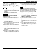
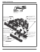
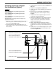
Figure 3-16: 1,200 Foot-Pounds of Torque
Rear Jack Installation
A rear jack assembly is available for use on the
Weatherproofer I combination finishing kits.
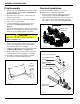
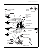
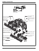
1. The rear jack assembly should be located on the
harrow arm tube assembly (See Figure 3-17.)
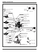
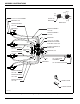
2. Slide rear jack mount plate onto 3/4-10 x 5 hex head
cap screws on top of harrow arm tube and hold in
place with 3/4-10 hex lock nuts (See Figure 3-18.)
Figure 3-17: Rear Jack Location
Figure 3-18: Rear Jack Installation
Tighten all 1-3/4” nuts to 1,200 foot-pounds of
torque (See Figure 3-16.)
300
POUNDS
PULL
4 FOOT
2 d410 010943
HARROW ARM
TUBE ASSEMBLY
REAR JACK
(STORED)
rear jack stored
rear jack inst
3/4-10 HEX LOCK NUT
REAR JACK MOUNT
PLATE
HARROW ARM
TUBE
3/4-10 X 5 HEX HEAD
CAP SCREW
REAR JACK
ASSEMBLY