
User Manual

ASSEMBLY INSTRUCTIONS
3-33
Finishing Conditioner Reel
Installation (Option)
NOTES
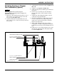
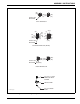
Refer to Figure 3-21 for hydraulic diagram.
See Figure 2-6 for finishing conditioner reel placement
dimensions.
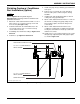
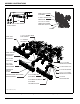
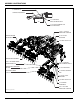
1. Attach reel arm assemblies to rear frame in second
hole from top using 1-8 x 7-1/2 hex head cap screw,
5” pivot bushing, and hex lock nut (See Figure 3-24.)
2. Attach reel arms w/ extension assemblies to rear
frame using 1-8 x 7-1/2 hex head cap screws and
hex lock nuts.
3. Attach 17” spring assembly and 2-1/2 hydraulic
cylinder to lower hole on rear frame using cylinder
trunnion, cylinder trunnion stop, 1/2-13 x 2-1/4 hex
head cap screw, and split lock washer.
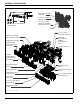
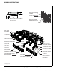
4. Install the 16 port hydraulic manifold to the rear fold
tower assembly at the rear of the center frame using
1/2-13 x 3-1/2 hex head cap screws and hex lock
nuts.
5. Install fittings into manifold according to Figures 3-21
thru 3-22.
6. Install hoses per Figures 3-21 thru 3-22.
7. Install steel plugs in any remaining open manifold or
valve ports.
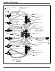
8. Attach conditioner reel/gang bar assembly to reel
arm assemblies using gang bar mount plates, 3/4-10
x 6 hex head cap screws, and double hex lock nuts.