
Owner's manual


ASSEMBLY INSTRUCTIONS
3-5
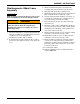
Main Wheel Lift Installation
1. Place 4” UHMW bearings onto rockshaft. Attach lift
bearing caps onto rockshafts using 3/4-10 x 2 hex
head cap screws and hex lock nuts.
2. Attach rockshaft to the frame assembly using lift
bearing cap, 3/4-10 x 2 hex head cap screws, and
hex lock nuts.
3. Attach rod end of each 4 x 16 hydraulic cylinder to
the lift using lift pins and 5/16 x 2-1/2 spring slotted
pins (See Figure 3-2.)
4. Install 90
o
adapters in each port of both 4-1/2 x 16
hydraulic cylinders.
IMPORTANT
Do not use 90
o
adapters with restrictors in ports of
lift hydraulic cylinders.
5. At this point, the lift cylinders need to be fully
retracted on both sides before the radius rod is
installed.
6. Assemble the wheels and tires to the hubs. Tighten
wheel bolts evenly to assure proper wheel alignment.
Wheel bolts should be tightened to 450 ft-lbs. of
torque. The hoist can then be removed.
7. Inflate the tire as recommended by the manufacturer.