Model 5211 Grain Drill Operator’s Manual LANDOLL CORPORATION 1900 North Street Marysville, Kansas 66508 (785) 562-5381 800-428-5655 ~ WWW.LANDOLL.
Table of Contents 1 Introduction Understanding Safety Statements . . . . . . . . . . . . . . . . . . . . . . . . . . . . . . . . . . . . . . . . . . . . . . . . 1-2 2 Standard Specifications 3 Assembly Instructions Press Wheel Assembly . . . . . . . . . . . . . . . . . . . . . . . . . . . . . . . . . . . . . . . . . . . . . . . . . . . . . . . . . 3-3 Small Seed Attachment Installation (Option) . . . . . . . . . . . . . . . . . . . . . . . . . . . . . . . . . . . . . . .
Opener – Press Wheel Adjustment . . . . . . . . . . . . . . . . . . . . . . . . . . . . . . . . . . . . . . . . . . . . . . . 4-26 Opener Scraper Adjustment . . . . . . . . . . . . . . . . . . . . . . . . . . . . . . . . . . . . . . . . . . . . . . . . . . . . 4-27 Opener Soil Strip Adjustment . . . . . . . . . . . . . . . . . . . . . . . . . . . . . . . . . . . . . . . . . . . . . . . . . . . 4-28 Walkboard . . . . . . . . . . . . . . . . . . . . . . . . . . . . . . . . . . . . . . . . . . . . . . . . . .
Chapter 1 Introduction The Landoll Model 5211 Grain Drill is a quality product designed to give years of trouble free performance. By following each section of this manual, your system will perform as designed for you and your operation CHAPTER 1 gives basic instructions on the use of this manual. CHAPTER 2 gives product specifications. These specifications supply lengths and measures for your equipment.
INTRODUCTION Understanding Safety Statements You will find various types of safety information on the following pages and on the machine signs (decals) attached to the vehicle. This section explains their meaning. The Safety Alert Symbol means ATTENTION! YOUR SAFETY IS INVOLVED! DANGER Danger means a life-threatening situation exists. Death can occur if safety measures or instructions on this label are not properly followed.
Chapter 2 Standard Specifications 5211 SERIES GRAIN DRILL MODEL NO. WORKING WIDTH ROW SPACING NO. OF OPENERS 5211-10 10-0”’ 7-1/2” 16 5211-10 10’-0” 10” 12 5211-12 12’-6”’ 7-1/2” 20 5211-12 12’-6” 10” 15 5211-15 15’-0” 7-1/2” 24 5211-15 15’-0” 10” 18 5211-20 20’-0” 7-1/2” 32 5211-20 20’-0” 10” 24 Specifications are subject to change without prior notification. TRANSPORT WIDTH 10-0”’ 10-0”’ 12’-6” 12’-6” 15’-0” 15’-0” 20’-0” 20’-0” ESTIMATED WEIGHT (LBS.
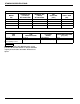
STANDARD SPECIFICATIONS 5211 SERIES GRAIN DRILL CAPACITIES MODEL NO. SEED BOX (BU) (3.25 BU/FT) W/O FERTILIZER DRY FERTILIZER (LBS.) SEED BOX (BU) (2 BU/FT) W/ FERTILIZER SMALL SEED (BU) 5211-10 32.50 20 1011 3.60 5211-12 40.60 25 1264 4.70 5211-15 48.75 30 1517 5.26 5211-20 65.00 40 2022 7.20 TIRE INFLATION TIRE SIZE 11L x 15 11L - 15 FI Farm Highway Service TIRE MANUFACTURER Goodyear Goodyear PLY/LOAD RATING INFLATION PRESSURE (psi) (max.
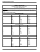
STANDARD SPECIFICATIONS LANDOLL CORPORATION GENERAL TORQUE SPECIFICATIONS (REV. 4/97) THIS CHART PROVIDES TIGHTENING TORQUES FOR GENERAL PURPOSE APPLICATIONS WHEN SPECIAL TORQUES ARE NOT SPECIFIED ON PROCESS OR DRAWING. ASSEMBLY TORQUES APPLY TO PLATED NUTS AND CAPSCREWS ASSEMBLED WITHOUT SUPPLEMENTAL LUBRICATION (AS RECEIVED CONDITION). THEY DO NOT APPLY IF SPECIAL GRAPHITE MOLY-DISULFIDE OR OTHER EXTREME PRESSURE LUBRICANTS ARE USED.
STANDARD SPECIFICATIONS LANDOLL CORPORATION HYDRAULIC FITTING TORQUE SPECIFICATIONS 37o JIC, ORS, & ORB (REV. 10/97) THIS CHART PROVIDES TIGHTENING TORQUES FOR HYDRAULIC FITTING APPLICATIONS WHEN SPECIAL TORQUES ARE NOT SPECIFIED ON PROCESS OR DRAWING. ASSEMBLY TORQUES APPLY TO PLATED CARBON STEEL AND STAINLESS STEEL FITTINGS ASSEMBLED WITHOUT SUPPLEMENTAL LUBRICATION (AS RECEIVED CONDITION). THEY DO NOT APPLY IF SPECIAL GRAPHITE MOLY-DISULFIDE OR OTHER EXTREME PRESSURE LUBRICANTS ARE USED.
STANDARD SPECIFICATIONS 19-9/16 SMALL SEED 25-3/4 10-5/8 14-1/2 5211-10_x_7.5_opener_placement Figure 2-1: 5211-10 Small Seed Placement (7.
STANDARD SPECIFICATIONS 20-3/8 FERTILIZER 24-1/2 7 14-1/2 5211-10 x 10_opener_placement Figure 2-2: 5211-10 x 10 Placement (10” Spacing Shown) 2-6 F-725-1213 Edition
STANDARD SPECIFICATIONS 4-9/16” SMALL SEED 4-1/4” DRIVE WHEEL 10-3/4” 6-1/2” 1/2” MARKER 1/2” MARKER 5211-12_5_x_7_5_opener_placement Figure 2-3: 5211-12-1/2 Marker and Small Seed Placement (7.
STANDARD SPECIFICATIONS 5-3/8” FERTILIZER 9-1/2” 4-1/4” DRIVE WHEEL 4” 5211-12_5_x_10_opener_placement Figure 2-4: 5211-12-1/2 Fertilizer Placement (10” Spacing Shown) 2-8 F-725-1213 Edition
STANDARD SPECIFICATIONS 17-13/16 17-13/16 16-5/8 COMPRESSOR 5210-12.5_x_7.5_3_pt_placement Figure 2-5: 5211-12-1/2 3 Point Placement (7.
STANDARD SPECIFICATIONS 12-3/4” SMALL SEED 5-1/2” MARKER 25-3/4” 14-1/2” DRIVE WHEEL 2-3/8” 5-1/2” MARKER 5211-15_x_7_5_opener_placement Figure 2-6: 5211-15 Marker and Small Seed Placement (7.
STANDARD SPECIFICATIONS 14-1/2” DRIVE WHEEL 12-7/8” FERTILIZER 24-1/2” 5-5/8” 5211-15_x_10_opener_placement Figure 2-7: 5211-15 Fertilizer Placement (10” Spacing Shown) 2-11
STANDARD SPECIFICATIONS 12-1/16 12-1/16 5-1/2 MARKER 5-1/2 MARKER 18-1/8 COMPRESSOR 5210-15_x_7.5_3_pt_placement Figure 2-8: 5211-15 3 Point Placement (7.
STANDARD SPECIFICATIONS 25-3/4” 16-7/8” SMALL SEED 16-7/8” SMALL SEED 14-1/2” DRIVE WHEEL 12-3/4” MARKER 4-1/4” SEED DRIVE 12-3/4” MARKER 4-1/4” SEED DRIVE 5211-20_x_7_5_opener_placement Figure 2-9: 5211-20 Marker and Small Seed Placement (7.
STANDARD SPECIFICATIONS 24-1/2” 17-5/8” FERTILIZER 14-1/2” DRIVE WHEEL 4” SEED DRIVE 17-5/8” FERTILIZER 4” SEED DRIVE 5211-20_x_10_opener_placement Figure 2-10: 5211-20 x 10 Fertilizer Placement (10” Spacing Shown) 2-14 F-725-1213 Edition
STANDARD SPECIFICATIONS 12-3/4” MARKER 1-11/16” DRIVE WHEEL 12-3/4” MARKER 1-3/8” COMPRESSOR 1-11/16” DRIVE WHEEL 5210-20 3 pt placement Figure 2-11: 5211-20 3 Point Placement (7.
STANDARD SPECIFICATIONS Ø .406 34-1/4 34-1/4 1 12 7-1/2’ SEED BOX (P/N 154842) Ø .406 2 46 46 1 2 12 10’ SEED BOX (P/N 143932) Ø .
Chapter 3 Assembly Instructions Your new 5211 Grain Drill comes nearly completely assembled from the factory and ready to go to the field. This section includes press wheel and option assembly procedures. To insure alignment of assemblies, leave the nuts loose until completion of final assembly. Use lock washers or flat washers as specified. Spread all cotter pins. After completion of final assembly, tighten all nuts evenly to prevent misalignment, distortion or binding.
ASSEMBLY INSTRUCTIONS AIR OPENER ASSEMBLY 3/4-10 HEX LOCK NUT PRESS WHEEL ASSEMBLY PRESS WHEEL ARM PIN press wheel assembly Figure 3-1: Press Wheel Assembly 3-2 F-725-1213 Edition
ASSEMBLY INSTRUCTIONS Press Wheel Assembly 1. Attach each press wheel assembly to each air opener assembly on the Grain Drill using press wheel arm pin and 3/4-10 hex lock nut (See Figure 3-1.) DANGER Opener blades are extremely sharp. Exercise extreme care when working on or near opener blades. Do not allow opener blades to roll over or fall onto any body part. Do not allow wrenches to slip when working near blades. Never push wrenches toward opener blades.
ASSEMBLY INSTRUCTIONS EXISTING MAIN SEED BOX ASSEMBLY EXISTING SMV BRACKET SMALL SEED BOX ASSEMBLY RELOCATED SMV BRACKET BEARING ASSEMBLY SMALL SEED SHIELD CHAIN ADJUSTMENT BRACKET 5211 small seed attach BEARING ASSEMBLY AND MOUNT Figure 3-2: Small Seed Assembly Overview 3-4 F-725-1213 Edition
ASSEMBLY INSTRUCTIONS Small Seed Attachment Installation (Option) Refer to 3-2 for small seed attachment overview. Use these instructions to install the optional small seed attachment to the rear main seed box of 5211 Grain Drill. 1. Attach the drill to the tractor and lower the unit to the ground. Leave the drill attached to the tractor while assembling the small seed attachment. This will prevent tipping of the drill while support stands are removed. 2.
ASSEMBLY INSTRUCTIONS 8. Attach the front of the chain adjustment bracket to the seed box bracket with the 1/2-13 x 1-1/4 hex head cap screw. 12. Install the 24 tooth drive sprocket and locking set screw on the end of the hex drive shaft (See page 2-16 for proper placement.) 9. Attach the slotted rear hole of the chain adjustment bracket to the outer hole of the small seed bearing assembly with a 5/16-18 x 1-1/2 round head square neck screw, 1” OD spacer and hex flange nut (See Figure 3-4.) 13.
ASSEMBLY INSTRUCTIONS Notes: 3-7
ASSEMBLY INSTRUCTIONS Page Intentionally Blank 3-8 F-725-1213 Edition
Chapter 4 Operation and Maintenance DANGER Never allow anyone to ride on the 5211 Grain Drill at any time. Allowing a person to ride on the machine can inflict serious personal injury or death to that person. DANGER Opener blades are extremely sharp. Exercise extreme care when working on or near opener blades. Do not allow opener blades to roll over or fall onto any body part. Do not allow wrenches to slip when working near blades. Never push wrenches toward opener blades.
OPERATION AND MAINTENANCE Tractor Preparation Grain Drill Preparation The Landoll 5211 Grain Drill is designed to be pulled by tractor equipped with a double lip or clevis type hitch. If your tractor is not equipped as such, you need to purchase the hitch from your local tractor dealer. Before attaching the Grain Drill, prepare the tractor as follows: 1. Inflate the rear tractor tires equally and add ballast according to the tractor operator’s manual. 1.
OPERATION AND MAINTENANCE Attaching Grain Drill To The Tractor WARNING The Grain Drill has positive and negative tongue weight. Use a locking-style hitch pin that is properly sized for the tractor drawbar and implement hitch. 1. Make sure the tractor drawbar is rated and adjusted properly for the weight of the drill hitch. 2. Measure the tractor drawbar and adjust the hitch clevis to the appropriate hitch mounting holes. 3. Carefully back the tractor into position.
OPERATION AND MAINTENANCE TRANSPORT LOCK STORAGE POSITION TRANSPORT LOCK INSTALLED FOR TRANSPORT 5211 transport lock locations Figure 4-2: Storage and Transport Position of Transport Locks Transport Locks 1. Transport lock pins are provided to secure the Grain Drill in raised position. Do not depend on hydraulics when working beneath raised equipment or when transporting. WARNING Install both transport locks before attempting to service, adjust, or transport raised equipment. 2.
OPERATION AND MAINTENANCE HITCH CLEVIS HEIGHT ADJUSTMENT 5210-hitch clevis Figure 4-3: Hitch Clevis Height Leveling the Hitch Clevis 1. The hitch clevis height should be adjusted to match the drawbar height of the tractor. This will allow the hitch to operate through its most efficient range and level throughout the field (See Figure 4-3.) 2. On a level surface, measure from the ground to the top side of the tractor drawbar. For drawbar heights 18” or lower use the lower hitch clevis holes.
OPERATION AND MAINTENANCE SMV SIGN SPEED IDENTIFICATION SYMBOL (SIS) DECAL HITCH WELDMENT SAFETY CHAIN 5211 hitch and safety chain Figure 4-4: Hitch and Safety Chain Transporting the Grain Drill 1. Check and follow all federal, state, and local requirements before transporting the Grain Drill. 2. The Grain Drill should be transported only by a tractor required for field operation. The implement weight should not exceed more than 1.5 times the tractor weight.
OPERATION AND MAINTENANCE 5. Slow down when driving on rough roads. Reduce speed when turning, or on curves and slopes to avoid tipping. Equipment altered other than the place of manufacture may reduce the maximum transport speed. Additional weight, added tanks, markers, harrow attachments, etc. may reduce the implements carrying capabilities. 6. A safety chain is provided with the implement to insure safe transport. DANGER Stay away from power lines when transporting, extending or folding implement.
OPERATION AND MAINTENANCE Compressor Operation 1. The Grain Drill is equipped with a small air compressor to make minor adjustments in system air pressure (See Figure 4-5.) When making large adjustments in system pressure, use shop or alternate air source. 2. Power to the electric air compressor is supplied through the main lighting harness. Connect the seven pin connector to the tractor.
OPERATION AND MAINTENANCE Air System Pressure 1. The air system pressure on the Grain Drill can safely operate in a range from 15 psi to 100 psi. A system pressure gauge is located at the front of the hitch and can be seen from the tractor to monitor system pressure (See Figure 4-6.) It is normal for the system air pressure to vary while working in the field. As the openers raise and lower over ground conditions, so will the system pressure vary. 2. Do not at any time operate the air system below 15 psi.
OPERATION AND MAINTENANCE Hydraulic Lift System 1. The hydraulic lift system contains cylinders plumbed together. The Grain Drill is equipped with a hydraulic lift system to raise and lower the unit from transport to planting position. 2. Before transporting make sure both lift cylinders and hitch cylinders are fully extended for maximum transport height. WARNING Escaping hydraulic fluid can cause serious personnel injury. Relieve system pressure before repairing, adjusting, or disconnecting.
OPERATION AND MAINTENANCE Loup II Drill Monitor Operation 1. The 5211 Grain Drill is equipped with a Loup II drill monitor. The drill monitor will monitor population from two sensors on each box, seed box levels on each seed box, as well as acres planted. 2. Population readings are 95% accurate for soybeans. When planting smaller seeds the population accuracy will be reduced. This does however give you a reliable indication that all sections are planting.
OPERATION AND MAINTENANCE Seed Meter Gate Adjustment The seed meter has an adjustable seed gate to accommodate various seed sizes for planting. The seed gate is adjusted by the handle on the outside of each seed meter. SEED GATE ADJUSTMENT HANDLE 1. Use the upper seed gate position when planting small seeds such as alfalfa, barley, rice, or wheat (See Figure 4-8.) 2. The middle seed gate position is for peas, small soybeans, etc. If excess cracking occurs, move the handle to the lowest position.
OPERATION AND MAINTENANCE Seed Rate Adjustment NOTE 1. The seeding rate is adjusted for each section with the threaded seed rate adjustment at one end of each drill section. The end seed meter next to the adjustment has an indicating scale for reference. Read the scale along the outside edge of the seed meter to determine the setting. The seeding rate should be set the same for all sections (See Do not force the seed meter shaft, damage will occur.
OPERATION AND MAINTENANCE Meter/Seed Rate Handle Adjustment 1. If the seed meter shaft is disassembled for maintenance or repair the seed meters and adjustment handle will need to be reset or zeroed to set the meters equally across the section. 2. To reset the meters, loosely reassemble the shaft, meters, spacers, locking collars etc. but leave the locking collars loose. 3. Tighten the threaded seed shaft adjustment to hold in place. 4.
OPERATION AND MAINTENANCE SEED RATE = (AVG SEED WEIGHT) X 65896 (NO. OF ROTATIONS) X (ROW SPACING) # SEEDS per ROW = (SEED RATE) X (SEEDS/LB) x (NO. OF ROTATIONS) x (ROW SPACING) 65896 # SEEDS per ROW = (POPULATION) X (NO.
OPERATION AND MAINTENANCE Seed Rate Calibration 1. The seed rate charts are in pounds per acre and based on an average seed size (See Figure 4-10.) Several factors can influence seeding rates: seed varieties, seed size, seed weight, seed treatment, seed cleanliness, tire pressure, tire slippage, and tire size. 3. To check the seeding rate: a. Adjust the seeding rate handle and drive type to the desired rate from the seed chart (See Figure 4-10.) b.
OPERATION AND MAINTENANCE Dry Fertilizer Combination Box 1. If the Grain Drill is equipped with the dry fertilizer option, it will have a combination seed/fertilizer box. The seed/fertilizer box is split for approximately 60% (2 bu/ft) seed and 40% (1.25 bu/ft) fertilizer. The box may be used for applying both seed and fertilizer, or converted to use both compartments entirely for seed. a.
OPERATION AND MAINTENANCE 3. When using both seed and dry fertilizer, fill the seed box keeping fill shield in closed position over fertilizer box (See Figure 4-13.) 5. When both compartments are being used for seed, open seed box lids and lift and rotate the fill shield over the rear of the seed box. This allows the compartments to be filled at the same time. This also improves access for maintenance and cleaning (See Figure 4-15.
OPERATION AND MAINTENANCE SEED BOX DOOR LATCH FERTILIZER WHEEL METER SEED METER FERTILIZER DOOR fertbox cleanout Figure 4-16: Fertilizer Box Clean Out Fertilizer Box – Clean Out 1. The fertilizer meters may be accessed for maintenance or cleaning by removing the door located at the bottom of the fertilizer meter assembly (See Figure 4-16.) 2. Remove any remaining dry fertilizer from inside the fertilizer compartment. Be prepared to catch the remaining fertilizer before opening the door.
OPERATION AND MAINTENANCE m174397 Figure 4-17: Fertilizer Box Chart Fertilizer – Rate Adjustment 2. The fertilizer chart is based upon average size dry fertilizer with a density of 65 lbs per cubic foot. If using a fertilizer with a different density, apply the following conversion factors, and use the closest rate for application (See Table 4-1.) 1. The dry fertilizer rate is adjusted by changing sprocket ratios for each section. See Figure 4-17 for desired settings.
OPERATION AND MAINTENANCE Fertilizer – Rate Calibration 1. Dry fertilizer can be affected by type, density, size, humidity, and field conditions. Operator should verify actual fertilizer rate output before planting. 2. To check the fertilizer rate: a. With a desired fertilizer rate and known density apply the above conversion factor and select rate from chart. If density is not known, use desired rate based on 65 lbs/ft3 from the chart. 3.
OPERATION AND MAINTENANCE m174412 Figure 4-18: Small Seed Seed Rate Chart Small Seed Rate Adjustment 1. The seeding rate adjustment for the optional small seeding attachment is located at the outer rear of each seeding box. The seeding rate should be set the same for all seeding boxes. On 15' & 20' drills there will be two adjustments to be made. 2. The small seeding rate is set independent of the seeding rate and drive type on the main seeding hopper. 3.
OPERATION AND MAINTENANCE Small Seed Meter Assembly/Adjustment 1. If the small seed meter shaft assembly is disassembled for maintenance or repair, the seed meters and seed rate adjustment will need to be reset or zeroed to set the meters equally across the seed box. 2. To reset the seed meters, remove all seed, chaff, and dirt from the seed box and seed meters. Reassemble the meters and drive shaft assembly, but leave the locking set collars, meter feed rolls and meter cut-offs loose on the shaft.
OPERATION AND MAINTENANCE NOTE: MAXIMUM TORQUE 30 FT. LBS. 3/4-16 HEX JAM NUT HEAVY SETTING AIR SPRING AIR SPRING PIVOT 1/2-13 X 1 HEX HEAD CAP SCREW NORMAL SETTING AIR OPENER ASSEMBLY air spring adjustment Figure 4-21: Air Spring Adjustment Air Spring Adjustment 1. The air pressure delivered to the air springs is the same for all openers. To be able to increase the down pressure for specific row units such as in wheel track locations, the air spring has two mounting positions.
OPERATION AND MAINTENANCE Opener Blade Adjustment 1. To insure peak performance of the opener assembly and maximum bearing life a proper opener blade pinch point should be maintained. The pinch point of the blades is the lower front point where the right and left opener blade come in contact with each other. DANGER Opener blades are extremely sharp. Exercise extreme care when working on or near opener blades. Do not allow opener blades to roll over or fall onto any body part.
OPERATION AND MAINTENANCE Opener – Press Wheel Adjustment 1. The seeding depth of each individual opener is controlled by the press wheel depth adjustment (See Figure 4-23.) To change the depth of each press wheel, raise the openers so there is not any weight on the press wheel. Pull up on the adjusting handle and slide the depth stop forward or rearward to obtain the desired seeding depth. Each notch represents approximately 5/16” in depth.
OPERATION AND MAINTENANCE AIR OPENER ASSEMBLY OPENER SCRAPER DISC BLADE ASSEMBLY 1/2-13 HEX FLANGE SPIRALOCK NUT 5530scraper Figure 4-24: Opener Scraper Adjustment Opener Scraper Adjustment 1. The opener is equipped with a scraper to keep the inside surfaces of the opener blades clean. In dryer conditions, the scraper can be adjusted farther away from the opener blades for greater clearance. In wetter conditions, it will be necessary to adjust the scraper blade closer to the opener blade.
OPERATION AND MAINTENANCE AIR OPENER ASSEMBLY 1/2-13 HEX FLANGE SPIRALOCK NUT SOIL STRIP BRACKET DISC BLADE ASSEMBLY PRESS WHEEL ASSEMBLY 1/2-13 X 1-1/4 RD HEAD SQ NECK SCREW SOIL STRIP 5530scraper2 Figure 4-25: Opener Soil Strip Adjustment Opener Soil Strip Adjustment 1. The soil strip runs along the side of the opener blade to reduce soil blow out of the seed trench. This will allow the soil to stay in position for more consistent filling of the seed trench and uniform coverage. 2.
OPERATION AND MAINTENANCE WALKBOARD IN RAISED POSITION SEED BOX WALKBOARD LATCH AIR OPENER ASSEMBLY PRESS WHEEL ASSEMBLY 5211walkboard Figure 4-26: Walkboard Adjustment Walkboard 1. The walkboard on the Grain Drill provides a stable platform to work from while filling the seed box (See Figure 4-26.) WARNING 2. The walkboard may be raised to allow easier service access to the openers. To raise the walkboard, lift at the center rear of the wallboard and rotate forward.
OPERATION AND MAINTENANCE Ladder Use and Transport Requirements WALKBOARD 1. When transporting the 5211 Grain Drill: a. The ladder should be in the raised position (laying across the top of the walkboard) and secured with the pin (See Figure 4-27.) LADDER b. The ladder should also be in the raised position when working in the field to prevent damage when working near trees, fences, power lines, etc. 2. When using the ladder: a.
OPERATION AND MAINTENANCE Hydraulic Row Markers (Option) 1. The Grain Drill may be equipped with optional hydraulic row markers. This will require an additional tractor remote to operate the markers. DANGER To prevent injury or death, stay clear of markers while folding/unfolding. Hydraulic failure can allow markers to raise or fall suddenly. DANGER To prevent injury or death from electrocution: stay away from power lines while transporting, folding, or unfolding markers.
OPERATION AND MAINTENANCE PUSH EXTENSION TUBE MARKER WELDMENT PULL SPINDLE ASSEMBLY MARKER BLADE ASSEMBLY 1/2-13 HEX NUT OUTER ARM ROW MARKER WELDMENT 1/2-13 X 3-1/2 RD HEAD SQ NECK SCREW AND HEX LOCK NUT U-BOLT Figure 4-29: Hydraulic Row Marker Adjustment Hydraulic Row Marker Disc Adjustment (Option) CAUTION Marker blades are very sharp. Use gloves when working around marker blades. 1. The marker disc blade may be adjusted to vary the mark left in the field. a.
OPERATION AND MAINTENANCE Coulter Hitch (Option) The Grain Drill may be equipped with an optional coulter hitch (See Figure 4-30.) Coulters may be used to provide additional tillage in front of the openers. The coulters operate on a separate hydraulic remote which operates independently of drill. A reference depth gauge is located on the left side of the hitch for coulter depth. Operation - The drill may be operated with or without the coulters lowered to the ground.
OPERATION AND MAINTENANCE LEFT DRIVE WHEEL ASSEMBLY 3 POINT HITCH RATCHET JACK RIGHT DRIVE WHEEL ASSEMBLY 5211-3pt Figure 4-31: 3 Point Hitch 3 Point Hitch (Option) The 5211 may be equipped with a 3 point hitch versus a pull hitch. The 3 point hitch is a standard width CAT III hitch and will attach to any tractor with a CAT III hitch or quick hitch. Drills equipped with the 3 point hitch will be equipped with drive wheels at each end of the main frame.
OPERATION AND MAINTENANCE Wheel Bearing Maintenance 6. Slide the triple-lip seal onto the spindle. Do not install the seal into the hub. Wheel bearing maintenance should be performed at the beginning of every season of use. Check the wheel bearings periodically for excessive end play. If needed, adjust or replace them using the following procedure: 7. Slide the inner bearing cone and hub onto the spindle. 1. Place the frame on blocks or stands sufficient to lift the tire clear of the ground. 2.
OPERATION AND MAINTENANCE Hydraulic Maintenance IMPORTANT 1. Check the tractor hydraulic fluid level per tractor owner's manual and after any leakage. Check fluid level with the cylinders in the retracted position. Lower the unit to the ground, and relieve hydraulic pressure before attempting to service any hydraulic component. 2. If a cylinder or valve leaks, disassemble the parts to determine the cause of the leak.
OPERATION AND MAINTENANCE 5210 hose color designations Figure 4-32: Hitch Hose Clamps and Color Designations JACK STORAGE POSITION JACK PARKING POSITION 5211 jack parking-storage positions Figure 4-33: Jack Parking and Storage Position 4-37
OPERATION AND MAINTENANCE Hose Identification Parking 1. The hydraulic hoses are color coded to help identify and match the attaching hoses on the Grain Drill. An identification decal is placed on the front of the hitch to help identify the hoses (See Figure 4-32.) 1. When unhitching the grain drill from the tractor, park the drill on a level area to prevent rolling and shifting. The Grain Drill has negative hitch weight and will need to lowered to the ground for parking.
OPERATION AND MAINTENANCE 1 2 3 4 5211 lube Figure 4-36: Lubrication Points 4-39
OPERATION AND MAINTENANCE LUBRICATION TABLE ITEM DESCRIPTION INTERVAL (Hours Unless Stated) NO. OF LUBE POINTS 1 Coulter Hitch Lift - Lower Rockshaft Bearing Cap 2 50 2 Coulter Hubs 1 each 50 3 Marker Arm 4 50 4 Coulter Hitch Lift - Upper Rockshaft Bearing Cap 2 50 Table 4-2: Lubrication Table Lubrication Maintenance Storage 1. Table 4-2 specifies the lubrication points and intervals on the 5211 Grain Drill.
OPERATION AND MAINTENANCE Notes 4-41
OPERATION AND MAINTENANCE Page Intentionally Blank 4-42 F-725-1213 Edition
Chapter 5 Troubleshooting Guide The Troubleshooting Guide, shown below, is included to help you quickly locate problems that can happen using your 5211 Grain Drill. Follow all safety precautions stated in the previous sections when making any adjustments to your machine. PROBLEM PLANTING TOO DEEP PLANTING TOO SHALLOW UNEVEN SEED DEPTH PROBABLE CAUSE SOLUTION Incorrect depth Adjust press wheel height (See “Opener – Press Wheel Adjustment” on page 4-26.
TROUBLESHOOTING GUIDE PROBLEM SECTIONS PLANTING AT DIFFERENT RATES UNEVEN SEED SPACING OPENER DISCS NOT TURNING FREELY PRESS WHEELS NOT COMPACTING THE SOIL AS DESIRED PRESS WHEEL OR OPENERS PLUGGING AIR SPRING LEAKING AIR AIR SYSTEM LEAK - FAST 5-2 PROBABLE CAUSE SOLUTION Seed rate adjustment not the same on all sections Adjust seed rate. Drive types (sprocket ratio) not the same on all sections Change to same drive type on all sections. Seed meter out of adjustment Reset seed meters.
TROUBLESHOOTING GUIDE PROBLEM AIR SYSTEM LEAK - SLOW PROBABLE CAUSE Air leaking thru air compressor filter Check valve leaking. Replace check valve Air line/fitting connection leaking Air lines ends must be cut square, and not scratched. Recut air line end if necessary. Push-in fitting lock ring when inserting or removing air lines. Air relief valve leaking Clean or replace air relief valve. NOTE Use a spray bottle with a soapy water solution to check for the following leaks.
TROUBLESHOOTING GUIDE 5-4 F-725-1213 Edition
Equipment from Landoll Corporation is built to exacting standards ensured by ISO 9001:2008 registration at all Landoll manufacturing facilities. Model 5211 Grain Drill Operator’s Manual Re-Order Part Number F-725-1213 LANDOLL CORPORATION 1900 North Street Marysville, Kansas 66508 (785) 562-5381 800-428-5655 ~ WWW.LANDOLL.COM Copyright 2010.