® SOIL BUILDER Coulter Chisel - Extended Frame Models: SB, HSB 71-1 through 131-1 Operator’s Manual s LANDOLL CORPORATION 1900 North Street Marysville, Kansas 66508 (785) 562-5381 800-428-5655 ~ WWW.LANDOLL.
Contents ontents Introduction . . . . . . . . . . . . . . . . . . . . . . . . . . . . . . . . . . . . . . . . . . . . . . . . . . . . . . . . . . . . . . . Location Reference . . . . . . . . . . . . . . . . . . . . . . . . . . . . . . . . . . . . . . . . . . . . . . . . . . . . . Parts Ordering . . . . . . . . . . . . . . . . . . . . . . . . . . . . . . . . . . . . . . . . . . . . . . . . . . . . . . . . . 3 3 3 Safety . . . . . . . . . . . . . . . . . . . . . . . . . . . . . . . . . . . . . . . . . . . .
Introduction Your Brillion Soil Builder is built with the best materials and workmanship available. It has been designed to give you years of trouble-free operation. SAFETY Study this manual carefully before attempting to assemble or operate this machine. A special section of this manual is devoted to assembly of the Coulter-Chisel. Refer to the “Setting Up Instructions” portion of this manual. ALERT This safety alert symbol is used to call your attention to instructions concerning personal safety.
S Safety afety S Suggestions uggestions Investigation has found that many farm accidents are caused by careless use of farm machinery. To minimize as much as possible the chance of personal injury or even death, insist that all people working with you or for you follow these instructions. Be sure to explain to the operator, in detail, the operation, maintenance, adjustments, and safe operation instructions contained in this manual.
Safety afety Signs igns There are three levels of hazard intensity that appear with the safety alert symbol on safety decals: DANGER, WARNING, and CAUTION. The level of hazard intensity is determined by the following defnitions: • Keep these signs clean so they can be observed readily. It is important to keep these decals cleaned more frequently than the machine. Wash with soap and water or cleaning solution as required. • Replace decals that become damaged or lost.
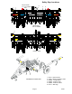
Safety Sign Locations 4 Center Decals on 11 & 13 Shank Only 3 6 3 4 4 3 REAR VIEW 11 & 13 SHANK 5 5 FRONT VIEW 4 4 2 1 DRAWBAR and SIDE VIEW Page 6 1. 8J310 - Caution Decal 2. 3J706 - Warning Hydraulic Leaks 3. 528938 - Orange Stripe 4. 528933 - Reflector, Red 5. 528934 - Reflector, Yellow 6.
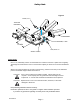
Safety Chain Figure 3 HHCS,1-8 x 3 TRACTOR DRAWBAR DRAWBAR FLAT WASHER,1" SAE 9" MAX NUT,LOCK 1-8 SAFETY CHAIN SoilBuilder SafetyChain Safety Chain WFPSafetyChain Use of a 10,100# safety chain is recommended if the machine is towed on a public road or highway. Total weight of towed machine must not exceed chain capacity as shown on the chain’s identification tag. Slack in the chain should be only enough to permit turning.
Operation peration Make sure the ratchet is stored away from the machine raising cylinder. The Brillion Soil Builder should be inspected prior to operation to see that all nuts and bolts are tight and to be sure that it is in good operating condition. (After the first few hours of initial operation, check bolts once again to be sure they haven’t loosened.) Hitch the coulter-chisel to the tractor drawbar.
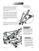
3-1/2” x 16” Cyllinder Operates Wheel Raising 3” x 8” Cyllinder Operates Coulters Do not set the coulters deeper than necessary Set the coulters to the desired depth by operating to cut the surface residue. Setting the coulters the hydraulic cylinder on the coulter depth control too deep in firm soil may prevent the shanks from (or by moving the pins to the proper holes if your properly penetrating the soil. machine is equipped with manually adjustable coulters.
LUBRICATION On your Brillion Soll Builder the following grease fittings should be greased after each 8 hours of operation. The four cast bearings on the coulter gangs, the six steel bearings on the wheel arms and rockshaft and the center bearing on the rockshaft. 8 HRS. Each season repack the wheel bearings and the walking beam pivot bearings on machines equipped with walking beam axles. 8 HRS. 791rev5-30-05 Also the four pins on the links from rockshaft to the wheel arms.
Daily Grease the ratchet jack as needed to prevent rusting, . On machines equipped with hydraulic coulter adjustment, grease the cast bearings daily. 8 HRS. If your machine is equipped with spring cushion shanks, grease the shank pivot after each 8 hours of operation. Coat the cylinder rods with grease to prevent the rods from rusting if the machine will be stored outside or for a prolonged period of time.
M Maintenance aintenance Fasteners Before operating your Brillion Zone Commander, check all hardware for tightness. Use the Tightening Torque Chart reproduced below as a guide. After a few hours use, check entire machine and tighten any loose nuts or bolts. Daily or periodic checks should be made thereafter. BOLT / NUT TIGHTENING TORQUES For Fine Threads Multiply Chart Values by 1.
SHIPPING BUNDLES SHIPPING BUNDLE CHECK LIST: Your Brillion Coulter-Chisel is shipped to you in separate assemblies. These assembly bundles are: QUANTITY PER MACHINE Bundle Name Frame - L.H. Frame - R.H. Coulter Gang Assembly Spring Rod Assembly Shank Hydraulic Cylinder Wheel Arms - L.H. Wheel Arms - R.H. Walking Beam Arm Assm., LH Walking Beam Arm Assm.
Assembly Assemblyy NOTE: SOME OF THE ILLUSTRATIONS FOUND THROUGHOUT THESE INSTRUCTIONS MAY NOT APPEAR EXACTLY LIKE YOUR MACHINE. THE SIZE OF THE MACHINE ILLUSTRATED MAY NOT AGREE WITH THE SIZE OF YOUR UNIT. ASSEMBLY OF MACHINES, HOWEVER, IS QUITE SIMILIAR ON ALL MODELS. DO NOT WORK UNDER MACHINE UNLESS IT IS BLOCKED UP SECURELY. • Set the frame about 36” high on blocks or other supports rated for 2,000 lbs. or higher. See figure 1.
SINGLE WHEEL ASSEMBLY Figure 2a-S 7J627 Bearings 7J627 Bearings Pivot Tube Wheel Arms HHCS, 3/4-10NC x 6” Lock washers, 3/4” 3/4-10NC Nuts IMPORTANT! Coat all bearing surfaces with grease before installing. ASSEMBLY OF SINGLE WHEEL - (7 & 9 SHANK) Position the wheel arm assemblies under the frame as shown in Figures 2a-S and 2b-S. Note that the wheel hubs and the longer end of wheel arm pivot tubes are located on the outward side of the machine.
Figure 2b-S Grease Fitting Roll Pin, 1/4 x 2” (in Collar) Pin, 1 1/4x 6 1/8” Center Bearing HHCS, 3/4-10 NC x 5-1/2” Lockwasher, 3/4” Nut, 3/4-10 NC Link Wheel Bolt, 1/2-20NF Tire, 11L x 15, 8 Ply Center the rockshaft, link ears rearward, on top of the frame directly above the wheel arm assemblies as shown in Figure 2b-S. Position a 7J627 bearing on each end of the rockshaft above the 10 x 4 frame tube. Be sure to align them with the appropriate set of holes.
TANDEM WALKING BEAM ASSEMBLY Rockshaft Figure 2a-T 7J627 Bearings (Use this position for 9-shank) 9-SHANK 7J627 Bearings HHCS, 3/4-10NC x 6 Lock washers, 3/4” 3/4-10 Nuts 7J627 Bearings 9-SHANK Alignment HHCS, 3/4-10NC x 6 1/2” Lock washers, 3/4” 3/4-10 Nuts 7J627 Bearings Wheel Arms IMPORTANT! Coat all bearing surfaces with grease before installing. 9-SHANK WALKING BEAM Position the wheel arm assemblies under the frame as shown in Figure 2a-T and 2b-T.
11 and 13 Shank Walking Beam Position the wheel arm assemblies under the frame as shown in Figure 2a-T2 and 2b-T2. Note that the inner wheel hubs are forward of the machine and the longer end of wheel arm pivot tubes is outward. Take the six bearings (7J627) and coat the inside bearing surfaces with grease. Place one 7J627 bearing per wheel arm on each end of wheel arm pivot tube. Position the assembly under the 10 x 4 frame tube with the outer bearing in the outer most set of holes.
Grease Fitting Figure 2b-T (9-Shank Configuration Pictured) (1) Roll Pin, 1/4 x 2” in Collar Pin, 1 1/4 x 6 1/8” Center Bearing HHCS, 3/4-10 NC x 5-1/2” Lockwasher, 3/4” Nut, 3/4-10 NC Link Wheel Bolt, 1/2-20 NF Tire, 11L x 15, 8 Ply Coat the center bearing with grease and install it on the rockshaft between the cylinder lift arms, with the chamfered end toward the front of the machine. Bolt in place with 3/4-10NC X 5-1/2” capscrews, lock washers and nuts.
INSTALL TRANSPORT LOCK • Install the transport lock with a 1-1/4 x 5-3/8” pin, two machinery bushings, and (2) 1/4 x 2” roll pins. Note that the leg of the angle that stops on the pin is down. • Slide the handle underneath the transport lock and bolt (2) 7J-661 straps to the tube end of the handle. Use a 1/2-13 NC x 4-1/2” capscrew and lock nut. Bolt through the round holes on the straps. Do not draw up tight as this must pivot. the rockshaft. Use 2 machinery bushings and (2) 1/4 x 2” roll pins.
COULTERS & COULTER CONTROL A. -HYDRAULIC COULTER CONTROL A few notes before you begin: •Use the cast bearings (in box #7J424, 7 & 9 shank; 7J424 and 7J425, 11 & 13 shank) and the hardware (in box #7J668, 7 & 9 shank; 7J668 & 7J860, 11 & 13 shank) to mount spring rockshaft on top of the machine. •Note that the 1/4 x 2 x 8” straps (four on 7 & 9 shank, seven on 11 & 13 shank) go under the cast bearings to act as spacers. The long studs go through these bearings as well as the bearings for the coulter gangs.
Figure 5 •The arms on the coulter frames should line up with the 6 pairs of lugs that point rearward on the spring rockshaft. • Place the bearing halves without grease f ttings on top of the coulter gang. • Stud Stop Keys Lock Nut, 5/8-11 Bearing w/ Grease Fitting 791rev5-30-05 Raise the gang up to get the studs through the bearings, then put a bearing half with grease f tting below the gang tube. Use the thin lock nuts from box 7J668 for both ends of the long studs.
Installation of Spring Rod Assemblies on Coulter Gangs with Spring Rockshaft Next insert and tighten them through the holes in the plates on the spring rockshaft and into the tapped holes in the block on top of the spring rod assemblies. See figure 6. Place the flat end of the spring rod assembly between the lugs on the coulter gang. Pin each spring rod assembly in place with 3/4 x 2-3/4” clevis pin and cotter pin. Attach the spring rod assembly’s upper end to the spring rockshaft.
Installation of Spring Rod Assemblies on Coulter Gangs with Spring Rod Holder Assembly Place the flat end of the spring rod assembly between the lugs on the coulter gang. Pin each spring rod assembly in place with 3/4 x 2-3/4” clevis pin and cotter pin. Place the spring rod holder assemblies, with chamfered plates rearward, onto the front frame tube centering them over the spring rod assemblies based on the coulter gangs. Hand tighten holders to frame with 3/4-10NC U-Bolts, lock washers and nuts. Figure 8.
SCRAPERS Scrapers for the Extended Frame Soil Builder are mounted on each of the pre-assembled coulter disc gangs. Coulter Disc Gang (7-Disc Gang shown) Scraper Tube Scraper SCRAPERS BETWEEN DISC GANGS Mount additional scrapers as shown between the disc gangs. For 11 and 13 shank models, mount two 7J854 scrapers with 7J855 straps and 1/2” capscrews, lockwashers and nuts. Put one bewteen the 1st and 2nd gangs and another between the 7 2nd and 3rd gangs.
Mount the drawbar. • Mount the drawbar to the lugs on the front of the frame with 1-7/16 x 8” long pins and 1/2 x 2” roll pins found in box 7J857 or 7J858. Ratchet Handle Storage Ratchet Handle Clevis pins, 1” x 2-1/2” Cotter pins, 3/16 x 2” • Slide together the upper and lower brace.
Mounting of shanks, points and shovels • Assemble the left hand and right hand shovels to • For assembly of the one piece shovels, the shanks with the plow bolts provided inside bolt onto shanks with the plow bolts provided. their box assemblies. • For normal operation the nuts on the spring • The right hand, three piece type of shovel mounting should be tightened so one inch assembly is illustrated at right. On all machine of thread is exposed.
7-Shank Single Wheel Attach the shanks in the positions indicated on the shank layout, Figure 11, below. Note: That the right and left on the shank layout indicate which direction that shank should throw the dirt. For normal operation the nuts on the spring mounting should be tightened so one inch of thread is exposed. Note: Refer to this Illustration for assembly of “7-Shank” models. R and L above refer to location of right and left hand shank assemblies.
9-Shank Single Wheel Front 7J656 L R L C Use 11L-15 6-8 Ply Tires 7J655 R R 15 L 15 15 15 L 15 15 15 R L 15 R Note: Refer to this Illustration for assembly of “9-Shank” models with Single Wheels.
9-Shank Tandem Wheel Front 7J656 R L L C Use 9.5L - 15 or 11L-15 6-8 Ply Tires 7J655 R 15 L R 15 15 15 L 15 L 15 15 15 R R Note: Refer to this Illustration for assembly of “9-Shank” models with Walking Beam Axles.
11 & 13-Shank Tandem Wheel Figure 11 Front (2) 7J656 13-shank only R R L L L C Use 9.5L - 15 or 11L-15 6-8 Ply Tires R R (2) 7J655 13-shank only L L L 15 15 L 15 15 R R 15 15 15 15 15 15 R 15 15 Note: Refer to this Illustration for assembly of “11-Shank” & “13-Shank” models with Walking Beam Axles.
MOUNT CYLINDERS Now install the 3-1/2 x 16 transport cylinder. (Refer to Figure 12a). •Use the pin furnished with the cylinder to attach the base end of the cylinder to the lug on the center of the frame. •Attach the rod end between the arms on the rockshaft with a 1-1/4 x 6-13/16 long pin, flat washers, and 1/4 x 2” roll pins. •Screw straight fittings into cylinder valve ports. Attach the 160” hoses to these fittings. The hoses go directly up to tractor.
Figure 13 90o Adapter 90o Adapter Hydraulic Cylinder, 3” x 8” Hydraulic Cylinder, 3 1/2” x 16” (4) Hydraulic Hoses, 3/8 x 160” Straight Adapter Hose Holder Male Tractor Tip 791rev1-10-08 Page 33 1K705
LED Warning Lights Red LED Lamp Amber LED Lamp Amber LED Lamp LED Warning Lights Harness Flasher Control Module 7Pin/4Pin WP Harness When plugging in the LED 7-pin connector: 1) Make sure the tractor has a good clean receptacle, free of dirt and corrosion. 2) Make sure the 7-pin connector is inserted ALL the way in. With tighter fitting pins, operator may think the connector is all the way in, but really isn’t.
LED Installation Dimensions CL 23"±1" Amber LED 23"±1" Red LED SMV Red LED Amber LED CL 38 3/4"±1" Amber LED 38 3/4"±1" Red Light Bar 11 and 13 shank Page 34A 1K705
Page 34B 1K705 7 Pin Harness Light Bkt. Tube Locknut,1/2-13 Locknut, 1/4-20 Light Bar HHCS, 1/4-20X1-1/2 HHCS,1/4X3/4 Connector Holder Locknut, 1/4-20 U-Bolt (Short) 1/2-13 x 3-1/2 Red LED Nut,1/4-20 HHCS,1/4-20X3 Light Module SMV Locknut, 1/4-20 Yellow Reflector Amber LED Red Reflector HHCS, 1/4-20X1-1/2 U-Bolt (Long) 1/2-13 x 4-9/16 Nut,5/16-18 Flat Washer,5/16 Orange Reflector Light Bkt.
LED Warning Lights Installation See pages 34, 34A and 34B for part placement and reference Light Bracket Tube Attach a Light Bracket Tube to the left front side of rear frame tube at a distance per page 34A. Secure with a longer 1/2-13 U-bolt and Flanged Locknuts. Red LED Lamp lens faces rearward Light Bar Route the 7 Pin Harness flat 4 pin plug end through the Light Bracket Tube's larger cutout (bottom) to the smaller cutout (top).
Machine Specifications (Subject to change without notice) Model Designation Basic model is denoted by : HSB - Extended Frame Soil Builder with Hydraulic Depth Controlled Coulters HSBH - Extended Frame Soil Builder with Hydraulic Coulters, & Hard-Surface 3-piece 4” Twisted Shovels HSBA - Extended Frame Soil Builder with Hydraulic Coulters, & Hard-Surface 1-piece 4” Twisted Shovels The number following relates to the shank combination of the machine.
Equipment from Landoll Corporation is built to exacting standards ensured by ISO 9001:2008 registration at all Landoll manufacturing facilities. SOIL BUILDER Coulter Chisel - Extended Frame Models: SB, HSB 71-1 through 131-1 Operator’s Manual Re-Order Part Number 1K705 LANDOLL CORPORATION 1900 North Street Marysville, Kansas 66508 (785) 562-5381 800-428-5655 ~ WWW.LANDOLL.COM ® Copyright 2014.