
User Manual


1K705
Page 16
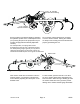
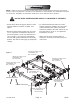
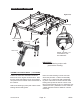
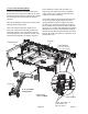
Center the rockshaft, link ears rearward, on top of
the frame directly above the wheel arm
assem-
blies
as shown in Figure 2b-S. Position a 7J627
bearing on each end of the rockshaft
above the
10 x 4 frame tube
. Be sure to align them with the
appropriate set of holes. Verify that the rockshaft
link ears line up with the wheel arm link ears.
Bolt in place with 3/4-10 NC x 6” capscrews, lock
washers and nuts.
Install the center bearing between the
cylinder
lift
arms, with the chamfered end toward the front of
the machine.
Bolt in place with 3/4-10 NC x 5 1/2” capscrews,
lock washers and nuts.
Install the links, oriented so the grease zerks are
accessible rearward, between the wheel arm and
rockshaft with 1 1/4” x 6 1/8” pins and
one
1/4” x 2”
roll pin per pin
keeping in mind that the roll pin goes
through the collar with the hole. See figure 2b-S.
Mount the tire and rim assemblies to the wheel
arms with the wheel bolts, 1/2-20NF x 1”
HHCS, 3/4-10 NC x 5-1/2”
Lockwasher, 3/4”
Nut, 3/4-10 NC
Pin, 1 1/4x 6 1/8”
Roll Pin, 1/4 x 2”
(in Collar)
Figure 2b-S
791rev5-30-05
Wheel
Bolt,
1/2-20NF
Link
Center Bearing
Tire, 11L x 15, 8 Ply
Grease Fitting