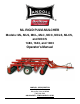
ML RIGID PULVI-MULCHER Models: ML, MLS, MCL, MLC, MCC, MCLS, MLCS, and MCCS 1483, 1643, and 1803 Operator’s Manual LANDOLL CORPORATION 1900 North Street Marysville, Kansas 66508 (785) 562-5381 800-428-5655 ~ WWW.LANDOLL.
Table of Contents 1 2 Introduction and Safety Information Introduction . . . . . . . . . . . . . . . . . . . . . . . . . . . . . . . . . . . . . . . . . . . . . . . . . . . . . . . . . . . . . . . . . . Description of Unit . . . . . . . . . . . . . . . . . . . . . . . . . . . . . . . . . . . . . . . . . . . . . . . . . . . . . . . . . Owner Assistance . . . . . . . . . . . . . . . . . . . . . . . . . . . . . . . . . . . . . . . . . . . . . . . . . . . . . . . . . Warranty Registration . . . . . . . . . .
Independent Tooth Control - Hydraulic Diagram . . . . . . . . . . . . . . . . . . . . . . . . . . . . . . . . . Light Installation . . . . . . . . . . . . . . . . . . . . . . . . . . . . . . . . . . . . . . . . . . . . . . . . . . . . . . . . . . Scrapers - Standard on Rear . . . . . . . . . . . . . . . . . . . . . . . . . . . . . . . . . . . . . . . . . . . . . . . . Rear Hitch - Optional . . . . . . . . . . . . . . . . . . . . . . . . . . . . . . . . . . . . . . . . . . . . . . . . . . . . . .
Chapter 1 Introduction and Safety Information Introduction Owner Assistance The implement described in this manual has been designed with care and built by skilled workers using quality materials and processes. Proper assembly and maintenance will provide you with satisfactory use for seasons to come. If customer service or repairs are needed, contact your Brillion dealer. They have trained personnel, parts and service equipment specially designed for Brillion products.
INTRODUCTION AND SAFETY INFORMATION Safety When applying decals to the implement, be sure to clean the surface to remove any dirt or residue. Where possible, sign placement should protect the sign from abrasion, damage, or obstruction from mud, dirt, oil etc. NOTE Investigation has shown that nearly 1/3 of all farm accidents are caused by careless use of machinery. Insist that all people working with you or for you abide by all safety instructions.
INTRODUCTION AND SAFETY INFORMATION Maintenance Safety • Block the implement so it will not roll when working on or under it to prevent injury. • Do not make adjustments or lubricate the machine while it is in motion. When inflating tires, use a clip-on chuck and extension hose long enough to allow you to stand to one side, not in front of or over the tire assembly. Use a safety cage if available. • Make sure all moving parts have stopped.
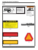
INTRODUCTION AND SAFETY INFORMATION Decals WARNING OK HERE (TRANSPORT LOCK HOLES) IMPORTANT EXCEPT IN TRANSPORT LOCK HOLE, DO NOT INSTALL PINS OK HERE (ANY HOLE FORWARD OF ANGLE BRACKETS) REARWARD OF ANGLE BRACKETS. DOING SO WILL RESULT IN DAMAGE TO MACHINE WHEN CYLINDER IS EXTENDED. NEVER HERE. (HOLES REARWARD OF ANGLE BRACKETS) 9J257 9J257 DO NOT GO NEAR LEAKS High pressure oil easily punctures skin causing serious injury, gangrene or death. If injured, seek emergency medical help.
528934 3K706 4K036 9J257 528934 I.D.
528933 4K036 2P151 4K036 528933 528934 9J257 4K039 528934 3K706 INTRODUCTION AND SAFETY INFORMATION Figure 1-5: Decal Placement - 2 of 2 1-6 1K044
Chapter 2 Assembly CAUTION Do not work on or under this machine unless securely blocked and supported by a hoist or tractor or by other sufficient means. 2. Position Inner Frame Tubes. Fasten Inner Frame Tubes to Front and Rear Tubes with 3/4”-10 X 2” HHCS, Lock Washers and Nuts. Ensure that the Inner Frame Tubes are square with the Front and Rear Frame Tubes. See Figures 2-1 and 2-2. 3. Position Outer Frame Tubes. Fasten with 5/8”-11 U-Bolts, Lock Washers and Nuts. See Figures 2-1 and 2-2.
ASSEMBLY Frame Assembly Dimensions NOTE “Left” and “Right” refer to directions seen as if standing behind the machine and facing in the direction of forward travel.
ASSEMBLY Rockshaft Installation Install Rockshaft using parts from the 8J061 Rockshaft Box Assembly. 1. Coat the bearing surface of the Bearing Assemblies with grease before fastening Rockshaft to Frame with 5/8-11” X 7” Bolts, Washers and Hex Nuts. 2. Install the base end of the 3 1/2” X 16” Hydraulic Cylinder using one of the vendor provided pins. The rod end of the Cylinder will be attached to the Rockshaft lug at the same time as the linkage. See Figure 2-5. 3.
ASSEMBLY 8J083 Link Installation 1. On the Front Frame Tube, Install the bottom 8J118 Spacer using a Bolt 1/2-13” X 5” and Lock Nuts 1/2-13”. Do not over tighten - Spacer must be able to rotate. See Figure 2-4. Spacer Bolt 1/2-13 X 5 Locknut 1/2-13 Figure 2-4: Spacer Installation 2. Attach the rod end of the Cylinder to the Rockshaft and the end of the 8J083 link having one hole. Use a 1” X 5 1/2” Pin and 1” Washers.
ASSEMBLY Pin, 1 X 5-1/2 1” Flat Washers Kilk Pin 1/4 X 1-1/4 8J083 Link Pin, 1 X 6-1/2 Spacer Hair Pin Cotter Roll Pin 5/16 X 2 Hinge Pin Rockshaft Roller Spacer Figure 2-5: Drawbar Link 2-5
ASSEMBLY Drawbar Installation 1. Attach Drawbar to the Frame using two 1” X 7 7/16” Pins, Flat Washers and 1/4” X 1 1/2” Cotter Pins. See Figure 2-6. 2. Attach Safety Chain with 1-8” X 3 1/4” Carriage Bolt, Flat Washers and Lock Nut. 3. Attach the Hose Support with 5/8-11” X 2” Bolt, Flat Washer and Lock Nut. 4. Install Jack. 5. Attach the Hitch with 1 1/4” X 8 3/4” Pin and 5/16 “X 2” Roll Pins and Washers.
ASSEMBLY Spring Linkage Assembly Install the Spring Linkage between the front Frame Tube and Drawbar. Use U-bolt, Springs, four Spring Caps and two 5/8" Lock Nuts. Also used are a 1" X 7 1/2” Pin, two 1" I.D. X 11/16" Spacers, four 1" Washers and two 1/4" X 2" Roll Pins. Install the Bumper at the top of post on the Drawbar using six 8J903 Spacers and two Hair Pin Cotters. See Figure 2-7.
ASSEMBLY Secure using 3/4-10” U-bolts, Lock Washers and Hex Nuts. End Bracket 3/4-10 Hex Nut Lock Washer Right Front End Bracket End Bracket Center Bracket Left Front Center Bracket Right Rear U-bolt Left Rear Further assembly at this time can be simplified by attaching the Drawbar and hoses to a tractor and using it to raise and lower the machine. To prepare for Roller installation, locate two 9J883 Center Bracket Assemblies. See Figure 2-8.
ASSEMBLY Install Roller Assemblies 1. Locate one Center Bracket Assembly at the center of the front frame tube and attach with 3/4-10” U-bolts, Lock Washers, and Nuts. See Figure 2-8. 2. Position one of the Shorter Roller Assemblies on the Center Bracket. Be sure clamp rings are towards the outside so assembly can be adjusted when needed. Crowfoot wheels have arrows on the spokes showing direction of rotation. (The one longer roller is used at the left rear corner.
ASSEMBLY Bracket Assembly Assemble the 8 Tooth Tube Brackets to the 8 vertical tube supports, one bracket to each support. For the 15’ machine only, there are two heavy-duty brackets provided for the inner rear tube supports that support the rear spring tooth tube. Use 1/2-13” X 6” Bolts and 1/2-13” Lock Nuts. If your machine is equipped with 5J609 S-Tines, mount these brackets to the top and middle holes. See Figure 2-10.
ASSEMBLY Tooth Tube Bracket Locations, 1483 and 1643 Models Tooth Tube Bracket Locations 1483 and 1643 Models Front 9J090 or 9J091 Bracket Rear Figure 2-11: ML 1483 - 1643 Tooth Tube Bracket Locations 2-11
ASSEMBLY Tooth Tube Bracket Locations, 1803 Model Tooth Tube Bracket Locations 1803 Model Front 9J090 or 9J091 Bracket 3K073 or 3K074 Bracket Rear Figure 2-12: ML 1803 Tooth Tube Bracket Locations 2-12 1K044
ASSEMBLY Tooth or Tine Installation After you have all eight brackets assembled, pencil mark the tooth locations on the tooth tubes. See Figure 2-17. Slide the tooth tubes through the brackets. Both of the tooth tubes must be centered on the machine - an equal length of tube extending out beyond the outer brackets. Slide each tooth up against the tooth tube bracket, this helps prevent the tube from sliding. See Figure 2-13. Then fix the tubes in place by assembling straps and U-bolts to each tooth tube.
ASSEMBLY S-Tine Points Install point using Cultivator Bolt and 3/8-16” Lock Nut.
ASSEMBLY Tooth Locations Pencil mark the tooth locations on the tubes.
ASSEMBLY Independent Tooth Control C-Tooth Installation Proper assembly shown below. See Figures 2-18 and 2-22.
ASSEMBLY Independent Tooth Control S-Tine Installation Proper assembly shown below. See Figures 2-19 and 2-22.
ASSEMBLY Non-Independent Tooth Control C-Tooth Installation Proper assembly shown below. See Figures 2-20 and 2-23.
ASSEMBLY Non-Independent Tooth Control S-Tine Installation Proper assembly shown below. See Figures 2-21 and 2-23.
ASSEMBLY Bracket Relationship per Tine Style Independent See Figures 2-18, 2-19, and 2-22.
ASSEMBLY Bracket Relationship per Tine Style Non Independent See Figures 2-20, 2-21, and 2-23.
ASSEMBLY WARNING Transport Hydraulic Diagram Escaping fluid under pressure can be nearly invisible and have enough force to penetrate the skin causing serious injury. Use a piece of cardboard, rather than your hands, to search for suspected leaks. Wear protective gloves & safety glasses or goggles when working with hydraulic systems. Tightening Procedure For JIC 37° Swivel Female Nuts 1. Check flare and seat for defects. 2. Lubricate the connection. Hyd. Cyl.
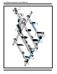
ASSEMBLY Independent Tooth Control Hydraulic Diagram EXT Adaptor (202702-8-8S) RET Hydraulic Cylinder 3 x 8 (3J603) Hydraulic Hose 285” (4K919) Adaptor (202702-8-8S) Male Coupler (141828) Figure 2-25: Independent Tooth Control - Hydraulic Diagram 2-23
ASSEMBLY Light Installation 1. Attach the Brackets to the Rear Frame using U-bolts 1/2” X 7 1/2” X 4 1/2”, Lock Washers and Hex Nuts. 2. Assemble the Dual Lamps to the Brackets using four 1/4” X 1-1/4” Screws and Lock Nuts. Make sure the Amber light is on top. 3. Assemble the wires and attach the Harness to the Frame using Cable and Hose Ties. See Figure 2-26.
ASSEMBLY Scrapers - Standard on Rear For 20" wheels, Scrapers are installed as shown. See Figure 2-27. The Scraper Brackets are located on the inside of the End Brackets and attach with U-bolts 3/8-16” X 3 1/4” X 2 7/16”, Flat Washers, Lock Washers, and Nuts. The Scraper Tubes are to be centered with respect to the machine and are fixed between the Scraper Bracket and a narrow 2" wide Scraper with U-bolt 3/8-16” X 3-1/4” X 2 7/16”, Flat Washers, Lock Washers, and Nuts.
ASSEMBLY Rear Hitch - Optional Attach the Rear Hitch between center frame tubes using U-bolts, Washers and 5/8-11” Hex Nuts as shown. See Figure 2-28.
ASSEMBLY Land Leveler - Optional Note: There are both Left and Right Brackets and Adjusting Angles. Left hand installation shown, Right hand is similar. The kit for the ML 1483 uses three brackets, the others use four. See Figure 2-29.
ASSEMBLY V Leveler - Optional Note: Position Leveler Weldment, centered in front of the Pulvi-Mulcher. Attach to Frame and Drawbar with Brackets and Hardware items shown. Vertical Adjustment may be required in the field. See Figure 2-30.
Chapter 3 Operation NOTE NOTE This chapter will cover the basic operation and procedures for the Landoll Brillion Pulvi-Mulcher. Be sure to read and understand the Safety Procedures and Cautions starting on See Page 1-1. Before operating your Brillion machine, check all hardware for tightness. Use the Tightening Torque Table in Chapter 4 as a guide. See Page 4-1. Level Adjustment To adjust the front of the machine higher during transport, add spacers between the bumper and Drawbar Center Mast.
OPERATION Spring Adjustment Transport Lock The Springs are used to cause the rear of the machine to lift before the front during the raising cycle (this prevents jolts when it shifts from rear-heavy to front-heavy). Tighten springs only to the level to accomplish this. See Figure 3-2. To prepare the machine for transport, raise it fully and install Transport Lock Pin. See Figure 3-2. The rear- most hole is used for pin storage during field operations.
OPERATION Depth Control Maximum operating depth of six (6) inches is obtained with depth pin in front hole. Each subsequent hole reduces the depth approximately one (1) inch. See Figure 3-2. In addition to the five depth settings, you have one other option; by using the optional hole setting you can achieve a working range of approximately 4” maximum down to “zero or completely inactive teeth.” See Figure 3-3.
OPERATION Arm Weldment Bracket Ground Line V-Leveler Weldment Set V-Leveler Weldment at or above ground level Figure 3-4: V-Leveler Side View Reflectors and SMV Sign Scraper Adjustment Reflectors and a slow moving vehicle sign (SMV) are required if the Pulvi-Mulcher is transported on a public road. See Figure 3-5. The roller scraper is designed to keep the roller from building up with moist soil during operation. Adjustment of the scraper will be necessary as the roller and/or the scraper wears.
Chapter 4 Maintenance General Torque Specifications (rev. 4/97) This chart provides tightening torques for general purpose applications when special torques are not specified on process or drawing. Assembly torques apply to plated nuts and capscrews assembled without supplemental lubrication (as received condition). They do not apply if special graphite moly-disulfide or other extreme pressure lubricants are used. When fasteners are dry (solvent cleaned) add 33% to as received condition torque.
MAINTENANCE Hydraulic Fitting Torque Specifications 37 degree JIC, ORS, &ORB (REV. 10/97) This chart provides tightening torques for general purpose applications when special torques are not specified on process or drawing. Assembly torques apply to plated nuts and capscrews assembled without supplemental lubrication (as received condition). They do not apply if special graphite moly-disulfide or other extreme pressure lubricants are used.
MAINTENANCE Tires Recommended inflation pressure for the 9.5L X 15-6 Ply tire is 30-32 PSI. Grease Daily Grease Daily Figure 4-2 Rockshaft Bearings Figure 4-1 Wheel Hub Wheel Bearing Maintenance Wheel bearing maintenance should be performed at the beginning of every season of use. Check the wheel bearing for excessive end play. If needed, adjust or replace them. Lubricating Wheel Hub: Grease Wheel Hubs every 40-60 hours. Repack Wheel Hub bearings annually before each season usage. See Figure 4-1.
MAINTENANCE C-Tooth Point Replacement Place the reversible point on the front of the C-tooth, line-up the two bolt holes, insert two 3/8-16 X 1-3/4 Cultivator Bolts and tighten using two 3/8-16 Lock Nuts. See Figure 4-3. As the C-tooth point wears, a replacement reversible point is available for installation.
MAINTENANCE Clamp Tightening Procedure The tightening procedure and torque requirement is critical in keeping in keeping the clamp tight and also has a significant affect on the bearing life of the axles with internal bearings. Clamp Tightening Procedure: 1. Check axle and clamp for burrs on mating surfaces. 2. Remove end play between wheels by sliding wheels toward the fixed end of the axle. 3. Position clamp snugly against the end wheel. 4.
MAINTENANCE Storage The service life of the ML Rigid Pulvi-Mulcher will be extended by proper off-season storage practices. Prior to storing the unit, complete the following procedures: • Completely clean the unit. • Inspect the machine for worn or defective parts. Replace as needed. • Repaint all areas where the original paint is worn off. • Grease all exposed metal surfaces. • Apply a light coating of oil or grease to exposed cylinder rods to prevent them from rusting.
Chapter 5 General Reference and Specifications Model Designation Optional Equipment The basic model is “ML” indicating mulcher having a frame for large diameter (20”) packer wheels. Specific ML machines are equipped with 20” wheels. Packer wheels are notched profile unless “C” appears as follows.
GENERAL REFERENCE AND SPECIFICATIONS Table provided for general use.
Document Control Revision Log: Date Revision 12/1991 Improvement(s) Description and Comments Initial Release 01/2004 690rev0104 Incorporated new parts 12/2012 690rev1212 Incorporated New Drawings, Parts and ECN’s, Independent Hydraulics. Updated to the Landoll format. 06/2013 690rev0613 Incorporated New Drawings, New Part Numbers, and Optional Equipment.
Equipment from Landoll Corporation is built to exacting standards ensured by ISO 9001:2008 registration at all Landoll manufacturing facilities. ML RIGID PULVI-MULCHER Models: ML, MLS, MCL, MLC, MCC, MCLS, MLCS, and MCCS 1483, 1643, and 1803 Operator’s Manual Re-Order Part Number 1K044 LANDOLL CORPORATION 1900 North Street Marysville, Kansas 66508 (785) 562-5381 800-428-5655 ~ WWW.LANDOLL.COM Copyright 2013.