
user manual


Laney
1010
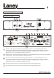
Input level indicator channel 1: Indicates the level of signal running through channel 1
Reset Button AMP 1 (CH1 + CH2): Should the unit be connected in error and experience a continuos overload
situation such as connecting the unit to an incorrect supply voltage or should the amplifier experience a
catastrophic component failure then the reset button will trip. This will cause the unit to completely shut down
and all power to the amplifier will be removed. Once the unit has tripped the reset button needs to be
pushed in. If the unit fails to reset itself immediately then the amplifier should be looked at by a qualified
technician. Consult your dealer.
Power switches: Used to switch each separate power amplifier unit on and off.
Reset Button AMP 1 (CH3 + CH4): Should the unit be connected in error and experience a continuos overload
situation such as connecting the unit to an incorrect supply voltage or should the amplifier experience a
catastrophic component failure then the reset button will trip. This will cause the unit to completely shut down
and all power to the amplifier will be removed. Once the unit has tripped the reset button needs to be
pushed in. If the unit fails to reset itself immediately then the amplifier should be looked at by a qualified
technician. Consult your dealer.
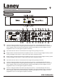
Input level indicator channel 3: Indicates the level of signal running through channel 3
Channel 3 input gain: Sets the level of the input signal to channel 3. The visual LED's give the user an
indication of the signal level running through the pre amplifier. The levels should be set as to minimise the
level of clipping. When the red LED is lit the signal is approaching clipping and some degree of sound
degradation may occur if the signal is clipped continuously.
Speakon Connector amp 4: Speakon connector for connecting external speaker. The signal present at this
connector is determined by the power amp mode setting (37) for this power amplifier. In Stereo Mode the
signal present is derived from Channel 4 input. In Dual Mono mode the signal present is derived from
Channel 3 input. In Bridge Mode NO signal is present at this connector.
Speakon Connector amp 2: Speakon connector for connecting external speaker. The signal present at this
connector is determined by the power amp mode setting (48) for this power amplifier. In Stereo Mode the
signal present is derived from Channel 2 input. In Dual Mono mode the signal present is derived from
Channel 1 input. In Bridge Mode NO signal is present at this connector.
XLR Input Channel 4: An XLR input option is provided for Channel 4 here. Pin connections for the XLR
connection are Pin 1 0V, Pin 2 Hot and Pin 3 Cold.
Jack Socket Channel 4: A jack-input option is provided for Channel 4 here
27
28
29
30
31
32
33
34
35
36
(TM)
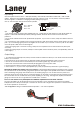
Speakons
For amplifiers, the most popular termination device on professional products has been the dual banana.
However, recent regulatory requirements in Europe have outlawed the use of the dual banana. It is
possible that similar regulatory controls will appear worldwide over the next few years. One solution to this
problem is to use the Neutrik Speakon™ connector. The major loudspeaker manufacturers have been
using Speakon connectors for the input termination on their products for several years now, so you can
be assured of the connector's reliability in the workplace. With Speakon (tm) connectors, you can plug
straight from the amp to the speaker, and start making those great sounds right away. The Speakon
connectors used on our amplifiers meet all known safety regulations. Once wired correctly, the
connector cannot be plugged in backwards, causing the type of inverted polarity situations that are
common with banana hookups. It will provide a safe, secure and reliable method of interfacing your
amplifier to the load.
™
Speakon Trademark of Neutrik AG
CA MANUAL