
user manual
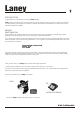


Laney
77
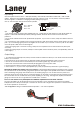
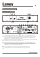
Channel 1 input gain: Sets the level of the input signal to channel 1. The visual LED's give the user an
indication of the signal level running through the pre amplifier. The levels should be set as to minimize the
level of clipping. When the red LED is lit the signal is approaching clipping and some degree of sound
degradation may occur if the signal is clipped continuously.
Bridge indicator: This LED indicates that the amplifier is running in bridged mode (14) When running in bridged
mode channel 1's level control acts as the master level control.
Channel 2 input gain: Sets the level of the input signal to channel 1. The visual LED's give the user an
indication of the signal level running through the pre amplifier. The levels should be set as to minimise the
level of clipping. When the red LED is lit the signal is approaching clipping and some degree of sound
degradation may occur if the signal is clipped continuously.
Input level indicator channel 1: Indicates the level of signal running through channel 1
Input level indicator channel 2: Indicates the level of signal running through channel 2
CA600/CA1500
Power Consumption
~50-60Hz
Warning
This Equipment must be earthed.
Attention.
Debrancher le cordon d’alimentation avant toute intervention.
Avis
Risque de choc electrique - ne pas ouvrir.
Warning
To reduce the risk of fire or electric shock do not
expose this appliance to rain or moisture.
Caution
To reduce the risk of electric shock do not remove covers.
No user serviceable parts inside. Refer servicing to
qualified personnel only.
CA1500 - 750Watts
CA600 - 350Watts
CA1500 - 750Watts
CA600 - 350Watts
k
c
o
L
k
c
o
l
n
U
k
c
o
L
k
c
o
l
n
U
k
c
o
L
k
c
o
l
n
U
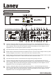
Caution
When using “BRIDGE”
mode only connect
speakers to the
“BRIDGE” terminal.
Min Load
4 Ohms
Bridge
Amp2
Min Load
2 Ohms
Min Load
2 Ohms
Amp1
Supply voltage
~115V
230V
~
1+ Amp1 Hot
1 - Amp1 Cold
2+Amp2 Hot
2 - Amp2 Cold
1+ Hot
1 - Cold
2+ n/a
2 - n/a
1+ Amp2 Hot
1 - Amp2 Cold
2+ n/a
2 - n/a
Made in the United Kingdom by BLT Industries Ltd.
Serial No:
!
CAUTION
RISK OF ELECTRIC SHOCK DO NOT OPEN
Dual Mono
Channel 2
Channel 1/
Dual Mono/
Bridge
Ground Link
XLR Pin Connections
Jack Pin Connections
Limiter
(Optional)
OffOn
Pin1 - 0V
Pin2 - Hot
Pin3 - Cold
Tip - Hot
Ring - Cold
Shield - 0V
In Out
Stereo
Bridge
Concept PowerConcept Power
00
C
A
6
1
0
Push to reset
Protect
A
Channel 1
Bridge
Channel 2
Clip
Signal
-12-
- 9 -
- 3 -
LaneyLaney
0dB
0dB
0dB
8
8
8
10
14
9
11
12
19
explanation of terms
2
8
41
15
16
17
18
13
5 6
Power
6
1
2
4
5
7 8a
CA MANUAL