
user manual


18
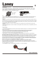
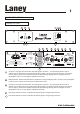
Power LED: Indicates the unit is powered up.
Reset Button: Should the unit be connected in error and experience a continuous overload situation such as
connecting the unit to an incorrect supply voltage or should the amplifier experience a catastrophic
component failure then the reset button will trip. This will cause the unit to completely shut down and all
power to the amplifier will be removed. Once the unit has tripped the reset button needs to be pushed in. If
the unit fails to reset itself immediately then the amplifier should be looked at by a qualified technician.
Consult your dealer.
Power Switch: Disable mains power to the unit.
Protect: This LED indicates that the output section of the CA amplifier has been run into extreme conditions
such as too low an impedance at too high a level for too long a period. In the situation that Protection is
engaged the output section is automatically disconnected from the speakers and then shut down. All the
other functions of the amplifier continue to function as normal but the amplifier will produce no sound. To
reactivate the amplifier it must be switched off, left for a few seconds and switched back on again, via the
main power switch (8a).
Speakon Connector amp 1: Used to connect an external speaker cabinet. The signal present at this
connection is dependent on the mode of operation of the power amp (14). In Stereo mode input signals
from channel 1 and Channel 2 are present at this socket. In Dual Mono mode only signals from Channel 1
are present. In Bridge mode this connector should not be used. Minimum impedance 2 Ohms.
Speakon Connector Bridge: Used to connect an external speaker cabinet when running the power amplifier
section in Bridged Mode (14). In Bridge mode only signals from Channel 1 are present. Minimum impedance
4 Ohms.
XLR Input Channel 2: An XLR input option is provided for Channel 2 here. Pin connections for the XLR
connection are Pin 1 0V, Pin 2 Hot and Pin 3 Cold.
Jack Socket Channel 2: A jack-input option is provided for Channel 2 here
Power amp mode switch: This switch selects the mode of operation of the CA power amplifier section. Three
modes of operation are available Stereo, Dual Mono and Bridge. In Stereo mode the two onboard power
amplifiers run independently supplying 300 watts (CA600) 750 watts RMS (CA1500) of each channel input to
each of the two output connections (10,19). In Dual Mono mode the signal present at Channel 1 input is sent
to both amp 1 output (10) and amp 2 output (19). In Dual Mono mode channel 2 is not active. The final
mode of the power amplifier is Bridge mode. In Bridge mode each individual power amplifier section is
summed together producing maximum output. In Bridge mode Channel 1 acts as the master channel.
Please note when selecting Bridge Mode the minimum impedance is 4 Ohms.
Ground Link Switch: This switched is used to reduce unwanted interference such as multiple earth loops etc
and does so by isolating the grounds of the input sockets only.
Limiter: Activates the onboard (Optional factory fitted) Limiter which prevents the output section being driven
into clipping allowing the amplifier to be run at maximum output without experiencing unwanted distortion.
Jack Socket Channel 1: A jack-input option is provided for Channel 2 here. When the power amplifier section
is running in either Dual Mono or Bridge mode, channel 1 acts as the master input channel.
XLR Input Channel 1: An XLR input option is provided for Channel 2 here. Pin connections for the XLR
connection are Pin 1 0V, Pin 2 Hot and Pin 3 Cold. When the power amplifier section is running in either Dual
Mono or Bridge mode, channel 1 acts as the master input channel.
Laney
88
7
8
9
10
11
12
13
14
15
16
17
Speakon Connector amp 2: Used to connect an external speaker cabinet. The signal present at this
connection is dependent on the mode of operation of the power amp (14). In Stereo mode input signals
from channel 1 and Channel 2 are present at this socket. In Dual Mono mode only signals from Channel 1
are present. In Bridge mode this connector should not be used. Minimum impedance 2 Ohms.
19
8a
CA MANUAL