Laney CA SERIES Power Amplifiers OPERATING MANUAL V1
Laney 2 INTRODUCTION Congratulations on your decision to purchase a Laney amplifier. Laney products are designed with ease of operation as a primary objective, however to ensure you derive the best from your new amplifier, it is important you take time to read this user manual and to familiarise yourself with the control functions and facilities available BEFORE SWITCHING ON After unpacking your amplifier check that it is factory fitted with a three pin 'grounded' (or earthed) plug.
Laney 3 IMPORTANT SAFETY INSTRUCTIONS WARNING: When using electric products, basic cautions should always be followed, including the following. 1. 2. 3. 4. 5. 6. 7. 8. 9. 10. 11. 12. 13. 14. 15. 16. 17.
Laney 4 Indroduction The CA range of amplifiers use a new power output topology. This enables a design which has all the high efficiency benefits of a class D type digital topology but without the usual draw backs of poor distortion and difficult to control EMC problems. The CA design uses microprocessor-controlled high frequency switching of state of the art output power FETs. Most switching amplifiers work at frequencies of around 200kHz.
Laney 5 Input Wiring The CA amplifier is factory set to +4dB input sensitivity, and internally selectable to either 0dB, +4dB or 26dB system. Setting the input sensitivity requires the removal of the top cover. If in any doubt, consult a qualified service engineer. For details on changing sensitivity setting see page 13 The 1/4“ Jack and 3pin XLR inputs are wired in parallel, 1 2 3 Pin1. Ground Pin2. Hot Pin3. Col Sleeve = Screen (GND) Ring = Cold Tip = Hot Tips. 1.
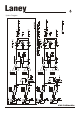
(via a single cable) (via a single cable) Laney 6 System Diagram CA MANUAL
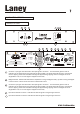
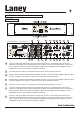
Laney 7 explanation of terms CA600/CA1500 2 1 4 7 Laney Concept Power Clip -3-9-12Signal 0dB Channel 1 5 8 8 Bridge 0dB Channel 2 6 Protect 0 A CA600 Min Load 4 Ohms 15 L oc 16 17 ck Made in the United Kingdom by BLT Industries Ltd.
Laney 7 8 8a 9 10 8 Power LED: Indicates the unit is powered up. Reset Button: Should the unit be connected in error and experience a continuous overload situation such as connecting the unit to an incorrect supply voltage or should the amplifier experience a catastrophic component failure then the reset button will trip. This will cause the unit to completely shut down and all power to the amplifier will be removed. Once the unit has tripped the reset button needs to be pushed in.
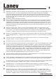
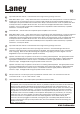
Laney 9 explanation of terms CA3000 53 21 Channel 2 8 Laney Clip -3 -9 -12 Sig 25 Channel 4 Clip -3 -9 -12 Sig Push To Reset 0 29 27 Push To Reset 30 Concept Power 0dB Channel 3 8 8 24 00 CA30 1 Clip -3 -9 -12 Sig 0dB 23 Bridge Protect Power Clip -3 -9 -12 Sig 0dB Channel 1 26 22 8 20 0dB 31 32 28 33 34 36 35 37 38 39 40 41 Two mains sockets on 115V model only! EUT R N N IK Min Load 2 Ohms IK EUT R Amp4 IK N Channel 4 Amp2 Min Load 2 Ohms Ground L
Laney 27 28 29 30 31 32 33 34 10 Input level indicator channel 1: Indicates the level of signal running through channel 1 Reset Button AMP 1 (CH1 + CH2): Should the unit be connected in error and experience a continuos overload situation such as connecting the unit to an incorrect supply voltage or should the amplifier experience a catastrophic component failure then the reset button will trip. This will cause the unit to completely shut down and all power to the amplifier will be removed.
Laney 37 11 Power amp mode switch: The CA3000 is a four channel power amplifier, Arranged as channels 1,2,3 and 4. These are configured as two totally separate stereo amplifiers. Channel 1 and 2 are treated as a pair, Channel 3 and 4 are treated as a pair. These channels can be used:(A) Stereo Mode. All channels run independently (B) Dual Mono. One signal sent to both amps. (C) Bridge.
Laney 42 43 44 12 Speakon Connector Bridge Speakon connector for connecting external speaker. The signal present at this connector is determined by the power amp mode setting (48) for this power amplifier. The Bridge speakon connector should only be used when the power amplifier mode switch (48) is set to Bridge. When in Bridge mode the signal present at the connector is derived from the input of Channel 3. Speakon Connector Amp 3: Speakon connector for connecting external speaker.
Laney 13 Specification Model Output Power per Channel @ 1%THD Bridge Bridge 2 Ohms 4 Ohms 8 Ohms 4 Ohms 8 Ohms CA600 300W 200W 160W 600W CA1500 750W 550W 350W 1500W Typical Total Power Consumption @ 1/3rd power music 4 Ohms 400W 220W 1000W 500W CA3000 750W 550W 350W 1500W 1000W 1000W x4 x4 x4 x2 x2 In bridge mode the amplifiers will operate comfortably at 4 Ohms enabling very high output levels to be achieved.
BLT Industries Ltd., Newlyn Road, Cradley Heath, West Midlands. B64 6BE. Tel: (0044) (0)1384 633821 Fax: (0044) (0)1384 639186 Http://www.laney.co.uk In the interest of continued product development BLT Industries Ltd. Reserves the right to amend product specification wihtout prior notification.