Laney Series Mixing Consoles Concept 10 Concept 16 USER MANUAL
Concept Concept 10 + Concept 16 User Manual 2 TABLE OF CONTENTS Page 2 Page 3 Page 4 Page 5 Page 6 Page 7 Page 8 Page 9 Page 10 Page 11 Page 12 Page 13 Page 14 Page 15 Page 16 Page 17 Page 18 Contents General Information Concept 10/16 Features Concept 10/16 Quick Start Guide Concept 10/16 Quick Start Guide Concept 10/16 Quick Start Guide Concept 10/16 Quick Start Diagrams Concept 10/16 Quick Start Diagrams Mic/Line Channel Information Mic/Line channel information (cont) Mic/Stereo channel information Mic
Concept THANK YOU We at Laney are extremely pleased that you have decided to select a Concept product for your mixing and we wish to reinforce your judgement by ensuring you get off to a flying start by including this comprehensive user manual to assist you in getting to know your equipment.
Concept Laney have been established in audio amplification for over twenty five years, during which time it has firmly established itself as a benchmark for audio products. SPECIAL FEATURES 6 or 10 Mic/Line channels 4 2 or 3 Mic/Stereo channels Feedback from musicians and recording engineers, supported by original design ingenuity, are the parameters applied by Laney's development engineers to all new products.
Concept Concept 10/16 Quick Start Guide This is a quick start guide so you can be using you mixer sooner rather than later - you can then refer to the detailed description later in this manual when you need.
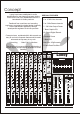
Concept You can send signals to FX using the Aux 1 and Digifx controls on the channels . The Aux 1 master send control adjusts the overall level sent to external FX units via the Aux 1 output socket . Signals from external FX units should be returned by the Stereo auxiliary - a rotary fader is then used to control the level of FX signal sent to masters, enabling a mix to established between FX signal and signal without FX 6 The Digifx control sends signals to the Digifx section.
Concept The Left and Right stereo mix are still available on the line outs should wish to connect additional power amps and speakers. 7 Advanced Set-up's The flexible routing facilities on you Concept 10/16 allow advanced set-ups to be achieved. The line outs/tape outs have a separate level control, this allows a slave amplifier to be connected and its volume level be controlled from the your mixer.
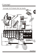
Concept Concept 10/16 Quick Set Up Guide connect your active/powered monitor here La ne y Connect more Vocals here AMP MIKED UP 8 Connect Vocals here O O O O O.O Laney connect tape/DAT/CD here for playback connect mic'd up guitar/Bass cabinet here D.I.
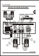
Concept Concept 10/16 Quick Set Up Guide Slave out to more Amps + Speakers here 9 Connect Effects or Loudspeaker controller here o o POWER AMPLIFIER o SEND MASTER RIGHT LINE OUT MASTER LEFT MONITOR INSERT MASTER LEFT LINE OUT RETURN O O O O O FX PROCESSOR o o Mixer `Sends' to FX/controller `Inputs' Mixer `Returns to FX/controller `Outputs' o MASTER RIGHT /LEFT + RIGHT INSERT RETURN o o o o DO NOT OBSTRUCT INLET VENTS DO NOT OBSTRUCT INLET VENTS SEND SPEAKER OUTPUTS POWER FUSE RAT
Concept Mic/Line channel 1) MIC INPUT (XLR) The input socket has been designed to accept both balanced and unbalanced signals from microphones with an XLR input connector. Good quality low impedance condenser or dynamic mic's should preferably be used for best effect, these will ensure the best possible results from hand held vocals or closely mic'd instruments.
Concept Mic/Line channel 6) continued Mon The Mon control is set for pre-fade operation for use as a monitor send.The signal passes to the feedback filter and monitor fader in the master section before leaving by the jack socket marked Mon. 11 LINE 7) INSERT AUX1 The AUX 1 is set for 'post fade' operation,it traditionaly being used as an effects send.The signal passes to the Aux 1 master send control before leaving by the socket marked Aux 1 Output.
Concept mic/stereo channel MIC 1) MIC INPUT (XLR) The input socket has been designed to accept both balanced and unbalanced signals from microphones with an XLR input connector. Good quality low impedance condenser or dynamic mic's should preferably be used for best effect, these will ensure the best possible results from hand held vocals or closely mic'd instruments.
Concept mic/stereo channel MIC 6) Mon continued 13 The Mon control is set for pre-fade operation for use a monitor send.The signal passes to the feedback filter and monitor fader in the master section before leaving by the jack socket marked Mon. STEREO LEFT 7) MONO AUX1 The AUX 1 is set for 'post fade' operation,it traditionaly being used as an effects send.The signal passes to the Aux 1 master send control before leaving by the socket marked Aux 1 Output.
Concept AUXILIARY INPUTS STEREO AUXILIARY /TAPE INPUT L 18) Stereo Auxilliary / Tape Input Phono (RCA) sockets are provided for the connection of tape/DAT machines. The signal to monitor and master outputs can be independently controlled via the controls labelled 'Tape to monitor' and 'Tape to master'. PFL monitoring of the tape to master signal is provided.
Concept Auxiliary Outputs 27) TAPE OUTPUT TAPE OUT L Phono (RCA) sockets are provided for the connection of tape / DAT machines for recording. The signal level is controlled by the Line out/Tape out level control. R 27 28) AUXILIARY 1 This is the Aux 1signal output. Signal is sent here by all the Channel Aux 1 controls .The master control for the Aux 1 output level is the Aux 1 Master Send Control.
Concept GRAPHIC EQUALISER A Graphic Equaliser is provided for fine 37) tuning of mixes and room acoustics 38) Centre frequencies are 80Hz,200Hz,430Hz,1.2KHz,2.2KHz,5.5KHz and 10.5KHz. Varying the 80Hz / 200Hz filters adjusts bass frequencies Varying the 430Hz,1.2KHz and 2.2KHz adjusts midrange frequencies Varying the 5.5KHz and 10.5KHz adjusts treble frequencies Laney 16 GRAPHIC EQUALISER 37 8dB 8dB 4dB 4dB 0dB 39) MASTER METERS The 'master meters' show the signal level to the power amplifiers.
Concept REAR PANEL FACILITIES DO NOT OBSTRUCT FAN APERTURE PIN -1GROUND PIN +1 SIGNAL PIN -1GROUND PIN +1 SIGNAL Insert loops are provided before each of the internal power amps .These are provided for the connection of speaker controlers , dynamics such compressors / limiters and feedback eliminators etc 1 jack socket is provided for send and 1jack socket is provided for return for each loop.
Concept MIX NOISE (measured 22Hz-22K,RMS,power amp level max) Master Up -80Bu 1 Channel 0dB -78dBu All channels 0dB -77dBu MIC CHANNEL (Fader 0dB ) MIC INPUT: Gain Max. 60dB + 10dB @ fader buffer Gain Min . 0dB + 10dB @ fader buffer Bandwidth 30Hz-20kHz -1dB E.I.N. (Equivalent Input Noise) -128dB (150R source Z) Distortion (mic to insets) typicaly <0.007% Maximum input +20dB Input Impedance 2K LINE INPUT: Gain Max. 36dB + 10dB @ fader buffer Gain Min.
Concept FURTHER NOTES Concept Manual