
Installation Instruction


INSTALLATION INSTRUCTION
Outdoor Flush Mount
FIG.1
Back Plate Dimensions
1 3/4”
Ø5 1/8”
1 3/8”
PREPARATION
1. Shut o the power at the circuit breaker and remove existing xture, including the crossbar.
2. Carefully unpack your new xture and lay out all the parts on a clear area. Be careful not to lose any small parts necessary for installation.
MOUNTING THE FIXTURE (Fig. 2)
3. Remove the mounting screw (C1), and take out the mounting plate.
4. Secure the mounting plate to the junction box using the junction box screw( B1). The side of the mounting plate marked
“GND” must face out.
CONNECTING THE WIRES (Fig. 2)
5. Connect the xture wire to junction box wires as shown in Fig. 2, making sure that all wire connectors (A1) are secured. If your outlet box
has a green or bare copper ground wire, connect the xture’s ground wire to it. Otherwise, connect the xture’s ground wire directly to the
back plate using the green screw provided. After wires are connected, tuck them carefully inside the junction box.
MOUNTING THE FIXTURE (Fig. 1)
6. Secure the canopy to the mounting plate with mounting screw (C1).
7. Rotate the glass onto the canopy, secure it with Allen screw (D1) using Allen wrench (E1).
8. To prevent moisture from entering the outlet box and causing a short, use clear caulking (i.e. indoor/outdoor silicone sealant) to outline the
outside of xture back plate where it meets the wall.
Fixture Wires
Black or
Smooth
Fixture Wires
White or
Ribbed
Fixture Wires
Bare wire
(Ground)
House Wires
Black
(Hot)
House Wires
White
(Neutral)
House Wires
Green or Bare Copper
(Ground)
Fig.2 Wiring
Junction Box
Caulking
Fig.3 Sealing
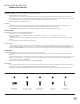
C1
B1
D1
E1
A1
Mounting Screw
Junction Box Screw
Allen Screw
Allen Wrench
Wire Connector
Junction Box
Ground Screw
Mounting Plate
Canopy
Glass
2