
User's Manual


COPYRIGHT ©2015 ALL RIGHTS RESERVED LANKE XUNTONG TECHNOLOGY CO.,LTD
TEL: +86 755 26674742 +86 755 26675941 E-mail: nrf@freqchina.com
6
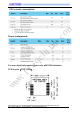
unit: mil
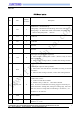
PIN Description
NO PIN
INPUT\
OUTPUT
Description
1 EN I
Enabled Pins,External Pull up:
Falling Edge:Module starts Broadcasting, and connect with device
Raising Edge:No matter what status of the module, the module will
enter into deep sleep mode. (420 nA)
2 TX O UART TX
3 RX I UART RX
4 — — Not used
5 — — Not used
6 CTS O
Input signal to wake up MCU (Optional)
0:Means module’s sending data to MCU , Master’s ready to receive
data from Module
1:Means no data sending to MCU, or Module data sending Finished
7 RTS I
Data output request to wake up module
0:Means MCU will send data out, and Module is waiting for the data
from MCU
1:Means no data sending to module, or MCU data sending finished
8 FLOW_CTR O
UART Flow Control:
0:UART can send data to module
1:Module is busy, UART can’t send data to Module
Note:TO Prevent UART data from losing, suggest to check the pin
status before MCU sending data, waiting for a falling edge , then send
data out ( wait for no longer than a broadcasting or an interval ) , see
the Chart 3-1 for reference.
9 GND — Power Ground
10 VCC —
Power Supply’
Positive(3 ~ 3.6V)
www.freqchina.com