Eagle V1.2 Imaging System Instructions for Use For use exclusively by authorized healthcare professionals in accordance with SBI-CIP 20-002: A prospective multi-center clinical study evaluating the use of PD G 506 A and the Eagle V1.2 Imaging System for the visualization of carcinoma during breast conserving surgery Contact Information: Address: SBI ALApharma Canada Inc. 123 Edward St., Suite 305 Toronto, ON M5G 1E2 Canada Email: SBI-ALApharma-PhV@spmd-safety.
Contents 1. Introduction .......................................................................................................................................... 6 i. CSS – Custom Sterile Sleeve .................................................................................................................. 6 ii. ECH – External Communication Hub..................................................................................................... 6 iii. DIS – Dark Imaging Sheet .....................
.1.6. CCD – Contact Charging Device .......................................................................................... 30 3.1.7. PSC – Protective Storage Cradle......................................................................................... 30 3.2. 3.2.1. Electromagnetic Compatibility .......................................................................................... 31 3.2.2. Radiation Output ..................................................................................
5.4. 5.4.1. Cleaning CCD ....................................................................................................................... 57 5.4.2. Disinfecting CCD ................................................................................................................. 58 5.5. 6. CCD – Contact Charging Device Cleaning and Disinfection ....................................................... 57 PSC – Protective Storage Cradle Cleaning and Sterilization..................................
PN 10232 Eagle V1.2 Instructions for Use Rev 1.
1. Introduction For use only by qualified investigators who have completed the Investigator Training Program in accordance with SBI-CIP 20-002, the Eagle V1.2 Imaging System is intended for performing intraoperative white light and Fluorescence Imaging of surgical cavities and excised tissues, including breast tissue obtained during breast cancer surgery. As sponsor of clinical trial SBI-CIP 20-002, SBI ALApharma Canada Inc.
o vi. A charging cradle for the Handheld Fluorescence Camera, providing a secure, flat surface for the HFC to rest while charging. Refer to Section 2.2.5 and Section 6.3.5 for full details. PSC – Protective Storage Cradle o A reusable stand to securely store and protect the Handheld Fluorescence Camera when not in use. Refer to 2.2.6 and Section 6.3.6 for full details. 1.1. Intended Use/Indications for use – Eagle V1.
tissue specimens and surgical cavity, beyond what can be visualized based on conventional surgical and imaging approaches, would provide surgeons with clinically useful real-time information. In patients undergoing breast conserving surgery, the presence of cancer in the margin of the resected lumpectomy and/or in the surgical cavity that is undetected by standard of care is a significant clinical challenge for surgeons and pathologists, and a risk to patients. The Eagle V1.
amino-4-oxo-pentanoic acid hydrochloride) for oral solution. When reconstituted in water, it can be administered exogenously to overload the cellular porphyrin metabolism and generate a build-up of PpIX. When ALA HCl is administered exogenously by oral route, the abundantly produced red fluorescent PpIX cannot be quickly converted to its final product, heme, by the enzyme ferrochelatase and therefore accumulates in cells. PpIX accumulates in cancer cells to a higher extent than in healthy cells.
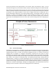
The main components a Fluorescence Imaging system are the following: 1. Fluorophores: Fluorescent molecules that can re-emit light upon light excitation. 2. Excitation source: Illumination source with a specific wavelength of light which is absorbed by the fluorophores, exciting the molecules and resulting in the emission of light at a longer wavelength. Emitted fluorescence can span ultraviolet, visible light, near-infrared light and infrared and beyond. 3.
1.4.2.2. Fluorophores – Protoporphyrin IX (PpIX) and Connective Tissue PpIX is a fluorophore that accumulates in cancer cells when a supply of exogenous ALA is supplied. When excited by 405 nm, PpIX emits red fluorescent light with a peak wavelength of approximately 635 nm. This red fluorescence can be used to visualize and locate the presence of PpIX fluorescent cancerous tissue. See (Figure 11). In addition, tissue autofluorescence is also emitted under 405 nm excitation.
1.4.2.4. Optical Filters – Dual Bandpass Filter In order to effectively visualize and image PpIX fluorescence, the 405 nm excitation light must be blocked from the imaging sensor. To accomplish this, a custom dual bandpass emission filter is placed in front of the camera image sensor thus preventing reflected or backscattered excitation light as well ambient room lighting from entering the image sensor.
The Eagle V1.2 Imaging System has received the following authorizations in order to conduct clinical trial SBI-CIP-20-002 in accordance with applicable United States and Canadian regulatory requirements per FDA and Health Canada: Table 1 Investigational Authorizations Investigational Product Drug Product: PD G 506 A Imaging Device: Eagle V1.
2. Eagle V1.2 Imaging System Contents Table 3 Eagle V1.2 Imaging System Component Depiction Part Number (P/N) HCF – P/N 10055 Handheld Fluorescence Camera Refer to Section 2.1 and Section 6.2 for full details. CSS – P/N 10180 Custom Sterile Sleeve Refer to Section 2.2.1 and Section 6.3.1 for full details. ECH – P/N 10206 External Communication Hub Refer to Section 2.2.2 and Section 6.3.2 for full details. PN 10232 Eagle V1.2 Instructions for Use Rev 1.
Table 3 Eagle V1.2 Imaging System Component Depiction DIS – Dark Imaging Sheet DIB – Dark Imaging Box CCD – Contact Charging Device PN 10232 Eagle V1.2 Instructions for Use Rev 1.0 Part Number (P/N) P/N 10171 Refer to Section 2.2.3 and Section 6.3.3 for full details. P/N 10117 Refer to Section 2.2.4 and Section 6.3.4 for full details. P/N 10066 Refer to Section 2.2.5 and Section 6.3.5 for full details.
Table 3 Eagle V1.2 Imaging System Component Depiction PSC – Protective Storage Cradle PN 10232 Eagle V1.2 Instructions for Use Rev 1.0 Part Number (P/N) P/N 10095 Refer to Section 2.2.6 and Section 6.3.6 for full details.
2.1. HCF – Handheld Fluorescence Camera The Handheld Fluorescence Camera (HFC) is the primary element of the Eagle V1.2 Imaging System. The HFC is a portable, handheld and batteryoperated imaging device, equipped with an AMOLED color display screen, and an optical head integrated with excitation and emissions optics to enter and image the surgical cavity. The optical head contains an ambient light sensor to detect ambient lighting conditions described in 6.2.2.2.5.
2.1.1.2. Range Finder The Range Finder positioned in the center of the optical head measures the distance of the optical head from the imaging target. The software user interface controlled by the HFC Display Screen (Section 6.2.1) instructs the operator to move closer or move away from the imaging target to achieve optimal imaging ranges. Refer to section 6.2.2.2.1 for full details on the Range Finder. 2.1.1.3.
2.2. Accessories and Consumables 2.2.1. CSS – Custom Sterile Sleeve The Custom Sterile Sleeve is a single use, ethylene-oxide (EtO) sterilized sheath to entirely cover the Handheld Fluorescence Camera while imaging surgical cavities. Refer to Section 6.3.1 for CSS Instructions for Use. Table 4 CSS Features 1. 2. The single use CSS is made from a clear, biocompatible plastic material that has been sterilized using EtO. The CSS is shaped to contour the Handheld Fluorescence Camera.
Table 4 CSS Features 5. Each CSS is accompanied by 2 small sterile bags to handle the HFC USB Hatch with sterile technique (see Section 6.3.1) while establishing ECH wireless configuration (Section 6.3.2.2) or ECH wired configuration (Section 6.3.2.3). 6. Each CSS is accompanied by 3 pieces of tape. Tape is used to secure the sterile bag around the HFC USB Cable for ECH Wireless Configuration (see Section 6.3.2.
Table 5 ECH Features 3. The ECH backs up all captured images and videos from the HFC onto the encrypted USB flash drive. 4. The ECH Numeric Pad allows the operator to enter a PIN to login and setup the ECH. 5. When connected to the ECH PC using an ethernet cable, the ECH Router allows HFC display casting wirelessly. Refer to Section 6.3.2.1 for details on ECH Wireless Configuration. The ECH DVI Link Assembly sends HFC imaging data received by the ECH PC to the ECH Display Monitor. 6.
Table 5 ECH Features A maximum of 5 power supplies connect to the ECH Power Bar: 8. 1) 2) 3) 4) 5) ECH Display Monitor ECH PC ECH DVI Link Rx ECH DVI Link Tx ECH Router 9. The ECH portable Cart holds and secures all ECH components and is accompanied by a 15-footlong Hospital Medical Power Extension Cord. 10. Refer to Section 4.3 for details on the ECH device label. 11. The ECH can be cleaned and disinfected with Intermediate Level Disinfection wipes in accordance with Section 5.2.
2.2.3. DIS – Dark Imaging Sheet The DIS is a single use, ethylene-oxide (EtO) sterilized non-fluorescent plastic sheet providing a consistent and standardized surface background for Fluorescence Imaging of excised tissues in the sterile field, or inside the Dark Imaging Box (Section 2.2.4 and Section 6.3.4). Refer to Section 6.3.3 for DIS Instructions for Use. Table 6 DIS Features 1. The DIS measures 10.5” (inches) long by 8.3” (inches) wide. 2.
2.2.4. DIB – Dark Imaging Box The Dark Imaging Box (DIB) is designed to cradle the Handheld Fluorescent Camera in a fixed position providing controlled and consistent conditions for imaging tissue specimens. The Dark Imaging Sheet is required to be placed on the Dark Imaging Box Tray per 6.3.3. Refer to Section 6.3.4 for DIB Instructions for Use. Table 7 DIB Features 1. Made from stainless steel and aluminium, the Dark Imaging Box has a wide base to stabilize the platform during imaging. 2.
Table 7 DIB Features 3. 4. Using the DIB Wheel, the DIB Imaging Platform is vertically adjustable to achieve correct imaging ranges as guided by the Range Finder per Section 6.2.2.2.2. The DIB ruler indicates the distance in cm (centimeters) between the tip of the HFC Optical Head and the DIB Imaging Platform. The DIB Tray is a sliding removeable tray for easy handling and orientation of imaging specimen, designed with a recess to secure the Dark Imaging Sheet into position per Section 6.3.3.
Table 7 DIB Features 5. The single use disposable DIB Covers enclose the specimen for a controlled and consistent imaging environment. Magnets embeddded around the top and bottom of the DIB align with the metal tabs on the DIB Covers to lock them in place. 6. Refer to Section 4.5 for details on the DIB device label. 7. The DIB can be cleaned and disinfected with Intermediate Level Disinfection wipes in accordance with Section 5.3. 2.2.5.
Table 8 Contact Charging Device Features The HFC is charged by placing it in the Contact Charging Device. 3. The retainer guard on the back side of the CCD secures the HFC while charging. The HFC battery begins charging when the HFC makes contact with the two charging pins on the top side of the CCD. 4. The bottom side of the Contact Charging Device has 6 anti-slip rubber feet to ensure it sits securely on a flat surface positioned in the non-sterile area of the imaging environment. 5.
2.2.6. PSC – Protective Storage Cradle The Protective Storage Cradle is designed to Safeguard the Handheld Fluorescence Camera and optical head when not in use (including during a surgical procedure) or during transportation. Refer to Section 6.3.6 for PSC Instructions for Use. Table 9 Protective Storage Cradle Features Made from stainless steel and acetal, the PSC has a cradle to rest the body of the HFC, a protective shaft to safeguard the HFC optical head, and a lock to secure the HFC once in position.
3. Safety Information This section is intended to provide users with safety information in order to operate the device safely and as intended. 3.1. Certifications 3.1.1.
• IEC 60601-1 Medical Electrical Equipment – Part 1: General Requirements for Basic Safety and Essential Performance • IEC 60601-1-2 Medical Electrical Equipment – Part 1-2: General Requirements for Basic Safety and Essential Performance – Collateral Standard: Electromagnetic Disturbances – Requirements and Tests 3.1.4.
The Eagle V1.2 Imaging System complies with Part 15 of the FCC Rules (USA) and ICES-3(B)/NMB-3(B) (Canada). Handheld Fluorescence Camera has an operational duty cycle of 5 minutes on, 15 minutes off. 3.2.1. Federal Communication Interference Statement We SBI ALApharma, 305-123 Edward St, Toronto, ON, M5G 1E2, Canada, 289-800-9455, declare under our sole responsibility that the Handheld Fluorescence Camera complies with complies with Part 15 Rules.
To avoid the risk of increased electromagnetic emissions or decreased immunity from such emissions, use only accessories, including power cables, recommended by SBI ALApharma Canada Inc. Connection of accessories not recommended by SBI ALApharma Canada Inc. will void product warranty and could result in malfunctioning of the HFC or other devices located in the area.
3.2.4. Radiation Output The Handheld Fluorescence Camera uses a miniature pulsed laser-based range finder to determine the correct distance between the device and wound for superior image quality. The laser module in the range finder emits light at 850 nm which is invisible to the human eye. The laser’s individual pulse duration is 3.33 ns and the pulse train is 52.3 ms at a 200 ms repetition rate. The laser complies with 21 CFR 1040.10 and 1040.11 except for deviations pursuant to Laser Notice No.50.
Warning Description Do not connect the Handheld Fluorescence Camera to a power supply using cables that have not been approved by SBI ALApharma Canada Inc. Do not attempt to open, modify, or disassemble the Handheld Fluorescence Camera which is ready for use once unpacked and charged. Do not charge or use the Handheld Fluorescence Camera in areas with potentially explosive atmospheres such as fueling areas or in areas where the air contains flammable or explosive chemicals or particles.
Warning Description The Handheld Fluorescence Camera utilizes auto-exposure to optimize the exposure settings based on lighting conditions. Images captured on the HFC are relative, not quantitative, and may not represent absolute fluorescence levels. Avoid strong electrical or electromagnetic fields, e.g. mobile phones, microwave ovens, etc.; which may result in temporary imaging error or inaccuracy. 3.3.2. General Cautions Caution Description Reflective objects (e.g.
Caution Description Some RF emitters (e.g. RFID) in the intended use environment may be concealed. The device could potentially be exposed to fields from these RF emitters without user awareness. Take the following precautions to prevent electromagnetic interference: 1. Maintain distance between portable and mobile RF communications equipment (transmitters) and the Handheld Fluorescence Camera 2.
4. Labelling This section provides users with information on device and accessory labelling. 4.1. HFC – Handheld Fluorescence Camera Device Label The following labels are applied to the HFC. 4.1.1. Symbols on HFC Device Label Table 10 Symbols on HFC Device Label # Symbol Meaning 1. Unique Device Identifier 2. Manufacturer Information 3. Device Model Name PN 10232 Eagle V1.2 Instructions for Use Rev 1.
Table 10 Symbols on HFC Device Label # Symbol Meaning Source 4. Reference Number ISO 7000 - 2493 5. Serial Number ISO 7000 - 2498 6. Date of Manufacture ISO 7000 - 2497 7. Indicating the device is to be used by qualified investigators only, in accordance with SBI-CIP-20-002 N/A 8. FCC ID N/A 9. ISED ID N/A 10. Warning for power cable use N/A 11. Duty Cycle N/A 12. WEEE Symbol. Dispose Electrical and Electronic Equipment. 13.
4.2. CSS – Custom Sterile Sleeve Device Label The following label is applied to the Custom Sterile Sleeve. 4.2.1. Symbols on CSS Device Label Table 11 Symbols on CSS Device Label # Symbol Meaning Source 1. Manufacturer Information 2. Indicating the device is to be used by qualified investigators only, in accordance with SBI-CIP-20-002 N/A 3. Device Model Name N/A 4. Reference Number ISO 7000 - 2493 5. Lot Number ISO 7000 - 2492 PN 10232 Eagle V1.2 Instructions for Use Rev 1.
Table 11 Symbols on CSS Device Label # Symbol Meaning Source 6. Date of Manufacture ISO 7000 - 2497 7. Date of Expiry ISO 7000 - 2607 8. Indicating the product was EO Sterilized ISO 7000 - 2501 9. Indicating the product should not be used if the packaging has been damaged or opened ISO 7000 - 2606 10. The product is for single use only ISO 7000 - 1051 11. The product is not made with natural rubber latex ISO 15223-1 12. The product is not to be resterilized ISO 7000 - 2608 13.
4.4. DIS – Dark Imaging Sheet Device Label The following label is applied to the Dark Imaging Sheet. 4.4.1. Symbols on DIS Label Table 12 Symbols on DIS Label # Symbol Meaning Source 1. Manufacturer Information 2. Indicating the device is to be used by qualified investigators only, in accordance with SBI-CIP-20-002 N/A 3. Device Model Name N/A 4. Reference Number ISO 7000 - 2493 5. Lot Number ISO 7000 - 2492 PN 10232 Eagle V1.2 Instructions for Use Rev 1.
Table 12 Symbols on DIS Label # Symbol Meaning Source 6. Date of Manufacture ISO 7000 - 2497 7. Date of Expiry ISO 7000 - 2607 8. Indicating the product was EO Sterilized ISO 7000 - 2501 9. Indicating the product should not be used if the packaging has been damaged or opened ISO 7000 - 2606 10. The product is for single use only ISO 7000 - 1051 11. The product is not made with natural rubber latex 12. The product is not to be resterilized ISO 7000 - 2608 13.
4.5. DIB – Dark Imaging Box Device Label The following label is applied to the Dark Imaging Box. 4.5.1. Symbols on DIB Label Table 13 Symbols on DIB Label # 1. Symbol Meaning Manufacturer Information PN 10232 Eagle V1.2 Instructions for Use Rev 1.
Table 13 Symbols on DIB Label # Symbol Meaning Source 2. Indicating the device is to be used by qualified investigators only, in accordance with SBI-CIP-20-002 N/A 3. Device Model Name N/A 4. Reference Number ISO 7000 - 2493 5. Serial Number ISO 7000 - 2498 6. Date of Manufacture ISO 7000 - 2497 7. Consult the instructions for use ISO 7000 - 1641 8. Unique Device Identifier 9. Product is Non-Sterile PN 10232 Eagle V1.2 Instructions for Use Rev 1.
4.6. CCD – Contact Charging Device, Device Label The following label is applied to the Contact Charging Device. 4.6.1. Symbols on CCD Label Table 14 Symbols on CCD Label # Symbol Meaning Source 1. Manufacturer Information 2. Indicating the device is to be used by qualified investigators only, in accordance with SBI-CIP-20-002 N/A 3. Device Model Name N/A 4. Reference Number ISO 7000 - 2493 5. Serial Number ISO 7000 - 2498 6. Date of Manufacture ISO 7000 - 2497 PN 10232 Eagle V1.
Table 14 Symbols on CCD Label # Symbol Meaning Source 7. The device is to be charged with power Adapter Cable PN 10115 ONLY N/A 8. Consult the instructions for use ISO 7000 - 1641 9. Unique Device Identifier N/A 10. CCD Power Supply Label N/A PN 10232 Eagle V1.2 Instructions for Use Rev 1.
4.7. PSC – Protective Storage Cradle Device Label The following label is applied to the Protective Storage Cradle. 4.7.1. Symbols on PSC Device Label Table 15 Symbols on PSC Device Label # Symbol Meaning Source 1. Manufacturer Information 2. Indicating the device is to be used by qualified investigators only, in accordance with SBI-CIP-20-002 N/A 3. Device Model Name N/A 4. Reference Number ISO 7000 - 2493 5. Serial Number ISO 7000 - 2498 6.
Table 15 Symbols on PSC Device Label # Symbol Meaning 7. Consult the instructions for use 8. Unique Device Identifier 5. Source ISO 7000 - 1641 N/A Cleaning and Disinfection Warning Failure clean, disinfect, and sterilize the Eagle V1.2 Imaging System may result in cross-contamination, and patient or user exposure to microbiological contamination. Warning Do not clean, disinfect, or sterilize the Eagle V1.2 Imaging System when energized.
cross-contamination, and patient or user exposure to microbiological contamination as described in Section 5.1. The External Communications Hub described in sections 2.2.2 and 6.3.1.2 positioned in the sterile field is cleaned and disinfected using intermediate level disinfection wipes as described in section 5.2. The Protective Storage Cradle described in sections 0 and 6.3.5 positioned in the sterile field is cleaned using intermediate level disinfection, and steam sterilized as described in section 5.5.
Table 16 Infrastructure, Materials, & Equipment Required for cleaning, disinfection, and sterilization # Eagle V1.
5.1. HFC – Handheld Fluorescence Camera Cleaning and Sterilization Before use, the Handheld Fluorescence Camera must be sterilized. SBI ALApharma Canada Inc. has validated and therefore recommends the use of mild soap and water as an effective cleaning agent before sterilizing the Handheld Fluorescence Camera with glutaraldehyde (2.5% solution). Following immediate use and before re-sterilization, SBI ALApharma Canada Inc.
Table 17Handheld Fluorescence Camera Cleaning Instructions 4. Thoroughly clean the HFC using mild soap and water. 5. With the naked eye, visually inspect the device in a well-lit area at a distance of approximately 12 inches to ensure all surfaces are clean. If necessary, repeat the cleaning steps above until the HFC is clean. 5.2.1. Sterilizing the HFC Table 18 Handheld Fluorescence Camera Sterilization Instructions The glutaraldehyde (2.
Table 18 Handheld Fluorescence Camera Sterilization Instructions 3. Before sterilizing, ensure the device has been properly cleaned according and that the USB-c hatch is closed and secured in place. 4. In the non-sterile area of the dedicated workspace, prepare a basin containing liquid chemical sterilant according the manufacturers instructions to achieve the appropriate dilution 5. Ensure the HFC is cleaned and completely dry prior to immersing in the sterilant. 6.
Table 18 Handheld Fluorescence Camera Sterilization Instructions 9. Completely dry the HFC by wiping with a sterile lint-free cloth. 10. Visually inspect the device to verify there are no signs of corrosion, discoloration, pitting, or cracked of seals. Visually inspect the HFC to ensure the optical glass (Item X in Figure X) is free of any visible material (e.g. fibers) or smudges (e.g. water stains). Use sterile lint-free cloth to wipe the optical glass if required. 11.
5.2.1. Cleaning ECH Table 19 External Communication Hub Cleaning Instructions 1. Wear impervious gloves such as latex gloves when handling Intermediate Level Disinfection Wipes. 2. Before cleaning, ensure the ECH and all components are UNPLUGGED from their power supplies, and ensure the all power supplies are UNPLUGGED from electrical outlets. 3.
Table 20 External Communication Hub Disinfection Instructions 5. The ECH and its components are now disinfected and ready for use. Observe sterile technique when transporting equipment from re-processing locations to points of use. 5.3. Dark Imaging Box Cleaning and Disinfection Caution Prior to disinfection, ensure surfaces are cleaned to remove organic matter as described in the sections below.
Table 22 Dark Imaging Box Disinfection Instructions 3. Thoroughly wipe crevices and areas that are difficult to reach. Where required, fold or bunch Intermediate Level Disinfection Wipes to push into crevices, corners, and areas that are difficult to reach. Use additional Intermediate Level Disinfection Wipes as necessary to ensure ALL SIDES and surfaces of the DIB including its Base, Cradle, Adjustment Wheel, Ruler, and Imaging Platform have been wet. 4. Once wet, allow the DIB to dry. 5.
5.4.2. Disinfecting CCD Do not continue with disinfecting the CCD, the CCD Power Supply, or cables unless the cleaning process described in Section 5.4.1 is completed. Effective disinfection can only be achieved after completing the cleaning process. Table 24 Contact Charging Device Disinfection Instructions 1. After cleaning, use at least two new Intermediate Level Disinfection Wipes to thoroughly wet ALL SIDES and surfaces of the CCD, the CCD Power Supply, and Cables. 2.
5.5.2. Sterilizing Protective Storage Cradle Do not continue with sterilizing the Protective Storage Cradle unless the cleaning process described in section 5.5.1 is completed. Effective sterilization can only be achieved after completing the cleaning process. Steam sterilize the Protective Storage Cradle according to the following instructions. Table 26 Protective Storage Cradle Sterilization Instructions 1.
6. Operating the Handheld Fluorescence Camera, and Eagle V1.2 Imaging System Accessories 6.2. HFC – Handheld Fluorescence Imaging Device Overview and Operation 6.2.1. Tactile Interface Table 27 Tactile Interface Buttons # 1. 2. Icon Name Video Button Camera Button PN 10232 Eagle V1.2 Instructions for Use Rev 1.0 Description Pressing the video button during White Light or Fluorescence Imaging begins video recording. Pressing the Video Button again stops and saves the video recording.
Table 27 Tactile Interface Buttons # Name Description 3. White Light Imaging button Pressing this button initiates White Light Imaging Mode (section 6.2.2.2.4) from Imaging Mode (Section 6.2.2.2) 4. Fluorescence Imaging button Pressing this button initiates Fluorescence Imaging (Section 6.2.2.2.5) from Imaging Mode (Section 6.2.2.2) 5. Battery Status LED Communicates battery charging status and battery level (Section 6.2.1.3) 6.
Table 28 Power On Instruction 2. During device start-up the SBI ALApharma Canada Inc. splash screen will be displayed. 3. Soon after, the Session Menu (section 6.2.2.1) is displayed. 4. Refer to Sections 6.3.2.2 and 6.3.2.3 for information on using the “Enable Casting” button and ECH connection status. 6.2.1.2. Shutdown / Power Off Table 29 Power Off Instruction 1. Access the Session Menu (section 6.2.2.1) to power off the device. 2.
Table 29 Power Off Instruction When prompted, press to return to the Session Menu, or press 3. to shutdown the device. 6.2.1.3. Battery Status LED The Battery Status LED (Table 27 item 61) • • • blinks Amber in color if the device is charging and the battery level is greater than 20% and less than 80%. blinks Green in color if the device is charging and the battery level is greater than 80% less than 100%.
6.2.2. Software User Interface 6.2.2.1. Session Menu Begin imaging or review captured images and videos from the Session Menu. Table 30 Session Menu Instruction After powering on, the Session Menu is displayed. To begin imaging, press 1. Or To review saved images and videos, press 2. Press “New patient session” to begin a new imaging session. 3. Press “Continue previous session” to continue the last imaging session. 4. Press “Demo session” to begin a demo imaging session. 5.
Table 31 New Patient Session Instruction 2. Before imaging, enter the Session ID or Patient ID using the onscreen keypad. Press to return to the Session Menu. Press 3. to begin imaging. Imaging Mode is initiated after pressing . White Light (Section 6.2.2.2.4) or Fluorescence Imaging (Section 6.2.2.2.5) can now be performed. 6.2.2.1.2. Continue Previous Session Continue a previous session to continue saving images and videos to the session.
6.2.2.1.3. Demo Session A Demo Session doesn’t require entry of a Session ID or patient ID and images are saved to Sessions named with prefix “000”. Table 33 Demo Session Instruction 1. Press “Demo session” to begin a demo session. Imaging Mode is initiated after pressing 2. . White Light (Section 6.2.2.2.4) or Fluorescence Imaging (Section 6.2.2.2.5) can now be performed. 6.2.2.1.4.
Table 34 Review Images and Videos Instruction 5. Pressing on a saved image will open the image. Press the Back button to return to the session. Pressing on a saved video will open the video. Pressing the Play button will play the video. 6. Pressing the Pause button playback. will pause video Press and drag the playback slider to the desired position to select video playback start point. Press the Back button to return to the session.
6.2.2.2. Imaging Mode Imaging Mode is enabled once a new patient session has been created (Section 6.2.2.1.1), a previous session is continued (Section 6.2.2.1.2), or a Demo Session has been started (Section 6.2.2.1.3). Figure 8 shows the Imaging Mode user interface. Figure 8: Handheld Fluorescence Camera’s User Interface under Imaging Mode PN 10232 Eagle V1.2 Instructions for Use Rev 1.
Table 35 Imaging Mode User Interface Icons # Icon Name Description 1. Imaging Field of View N/A Indicates the borders of the imaging field of view 2. Circle of Interest N/A Recommended imaging region for Fluorescence Imaging. Imaging in this region ensures optimal Fluorescence Imaging. 3. End Session Icon Pressing this button will end the current imaging session after prompting. 4. Device Information Icon Pressing this button will display device information.
Table 35 Imaging Mode User Interface Icons # Icon Name Description Ambient Light Sensor Warning Icon This icon appears overlaid in the top right corner of the Imaging Field of View when the Ambient Lighter Warning has been accepted 11. Range Finder (RF) These range icons appear in the bottom center of the Imaging Field of View when the camera sensor is too close or too far from the imaging target. 12. Temperature Gauge The temperature gauge communicates relative temperature to the operator. 10.
Table 36 White Light Imaging Instruction 1. Enter Imaging Mode per Section 6.2.2.2. 2. While in Imaging Mode, press the WL button on the right side of the HFC tactile interface (Section 6.2.1) or the White Light Imaging Icon on the right side of the Software User Interface (Section 6.2.2) to initiate White Light Imaging. 3. The white WL icon turns blue when the WL button on the tactile interface is pressed to begin White Light Imaging 4. 5. 6. 7.
6.2.2.2.5. Fluorescence Imaging Accessed through Imaging Mode, White Light Imaging can only be performed after creating a new patient session (Section 6.2.2.1.1), continuing a previous session (Section 6.2.2.1.2), or beginning a Demo Session (Section 6.2.2.1.3). Table 37 Table XX Fluorescence Imaging Instruction 1. 2. Enter Imaging Mode per Section 6.2.2.2. Fluorescence Imaging must be performed in the darkness.
6.2.2.2.5.1. Ambient Light Warning When attempting to initiate Fluorescence Imaging when incorrect ambient lighting conditions are detected, the following warning appears indicating that “ambient light is too bright for Fluorescence Imaging” Press to return to Imaging Mode. Take action to correct ambient light conditions by diminishing sources of light in the imaging environment until the FL icon located in the top right corner of the Imaging Mode’s user interface is circled in blue.
6.2.2.2.5.2. Interpretation of Fluorescence Images Table 38 provides exemplary white light and fluorescence images of grossly sectioned breast tissue specimens. Areas of red PpIX fluorescence are contrasted with areas of healthy tissue autofluorescence which typically appear predominately green and brown. Areas containing connective tissue typically appear green fluorescent. Areas composed predominately of adipose tissue typically appear dull pink or brown.
Table 38 Interpretation of Fluorescence Images White Light Images Fluorescence Images 2. 3. PN 10232 Eagle V1.2 Instructions for Use Rev 1.
Table 38 Interpretation of Fluorescence Images White Light Images Fluorescence Images 4. 5. 6.2.2.3. Saving Data Whenever an image or video is captured under White Light Imaging (Section 6.2.2.2.4) or Fluorescence Imaging (Section 6.2.2.2.5), it is automatically saved to the ECH Flash Drive. Saved data can be reviewed from the Sessions Menu described in section 6.2.2.1. 6.2.2.4. Exporting Data All data is saved to the ECH Flash Drive.
6.3. Accessories Overview and Operation 6.3.1. Custom Sterile Sleeve (CSS) Instructions for Use The Custom Sterile Sleeve can be sheathed around the Handheld Fluorescence Camera in two (2) ways to accommodate both ECH Wireless (Section 6.3.2.2) and ECH Wired (Section 6.3.2.3) Configurations. Observe sterile technique when mounting the CSS as described in the next Sections 6.3.1.1 and 6.3.1.2. 6.3.1.1.
Table 39 Custom Sterile Sleeve Wireless Configuration Instructions 4. 5. Prepare to remove the HFC USB Hatch with sterile technique by placing thumb and index finger inside one (1) small sterile bag provided with the CSS. Pinch-grip, twist, and pull the HFC USB Hatch to remove it. Use the small sterile bag to hold the HFC USB Hatch with sterile technique. Connect the HFC USB Cable to the HFC. 6. Position the HFC USB Cable 90° Type-C connector such that it points towards the inside of the HFC. 7.
Table 39 Custom Sterile Sleeve Wireless Configuration Instructions Link the HFC USB Cable to the ECH Link Cable while observing sterile technique. 8. Connect ECH Link Cable to ECH PC USB Port per Section 6.3.2.2 Step 8. Before proceeding to the next step in this instruction, verify successful connection between the HFC and ECH per Section 6.3.2.2 Steps 8 through 14. 9. 10. After verifying successful connection between the HFC and ECH per Section 6.3.2.
Table 39 Custom Sterile Sleeve Wireless Configuration Instructions Prepare to re-attach the HFC USB Hatch with sterile technique. 11. While pinch-gripping the HFC USB Hatch with the small sterile bag, push and twist the HFC USB Hatch to re-attach it. The HFC is now ready to be sheathed with the CSS. Slide the HFC into the CSS. Fit the CSS over the HFC optical head. 12. Ensure the CSS optical window snaps onto the optical head.
Table 39 Custom Sterile Sleeve Wireless Configuration Instructions 14. 15. Pull CSS slack material taut from the bottom and left, and wrap the HFC in a gift-wrap style. Pull off the adhesive backing from the CSS Tape while keeping the gift-wrapped CSS material in position. Lay the CSS Tape over the giftwrapped CSS material. 16. 17. Lay and push the CSS Tape firmly across the backside of the HFC body. Flip the HFC around and finish adhering the CSS Tape around the right front side of the HFC.
6.3.1.2. Custom Sterile Sleeve Wired Configuration Table 40 Custom Sterile Sleeve Wired Configuration Instructions 1. Ensure the External Communications Hub (ECH) is set up for ECH Wired Configurations per Section 6.3.2.3. Pull the CSS out of its packaging. 2. Unfold the CSS. Prepare the CSS, two (2) small sterile bags, and three (3) pieces of tape on a flat surface in the sterile field. Slide the HFC into the CSS. Fit the CSS over the HFC optical head. 3. 4.
Table 40 Custom Sterile Sleeve Wired Configuration Instructions 5. 6. 7. Pull to fully extend the telescopic HFC USB Cable Cover. Run the HFC USB Cable through the telescopic HFC USB Cable Cover Pull to align the HFC USB Cable 90° Type-C connector with the HFC USB Hatch, leaving enough slack to orient and manoeuvre the cable easily. Using provided tape, secure the opposite end of the HFC USB cable to the work bench, allowing sufficient slack to orient and manoeuvre the HFC during imaging.
Table 40 Custom Sterile Sleeve Wired Configuration Instructions 8. While holding the HFC USB Hatch, turn the small sterile bag inside-out to safeguard the HFC USB Hatch while not in use. Connect the HFC USB Cable to the HFC. 9. Position the HFC USB Cable 90° Type-C connector such that it points towards the inside of the HFC. Link the HFC USB Cable to the ECH Link Cable, while observing sterile technique. 10. Connect ECH Link Cable to ECH PC USB Port per Section 6.3.2.3 Step 8.
Table 40 Custom Sterile Sleeve Wired Configuration Instructions Pull the CSS taut over the body of the HFC. 11. 12. Position the sheathed HFC USB Cable along the bottom and left side of the HFC body. Ensure the HFC remains positioned in the top right of the CSS such that any CSS slack material hangs off the left side of the HFC, while the CSS Tape is flush with the right side of the HFC. Pull CSS slack material taut from the bottom and left, and wrap the HFC in a giftwrap style. 13.
Table 40 Custom Sterile Sleeve Wired Configuration Instructions 14. Lay and push the CSS Tape firmly across the backside of the HFC body, ensuring the CSS Tape contours along the sheathed HFC USB Cable positioned in Step 11. Flip the HFC around and finish adhering the CSS Tape around the right front side of the HFC. 15. The Handheld Fluorescence Camera is now sheathed in the Custom Sterile Sleeve using the ECH Wired Configuration (Section 6.3.2.3), and ready for Imaging per Section 6.2.2.2.
6.3.2. External Communications Hub (ECH) Instructions for Use Once assembled according to Section 6.3.2.1 The External Communications Hub can be configured in a wireless or wired fashion to cast the Handheld Fluorescence Camera’s display on to the ECH Display. The HFC display is cast wirelessly to ECH Display Monitor when the HFC is connected to the ECH PC, using ECH Router. Follow instructions in Section 6.3.2.2 to set up the ECH Wireless Configuration.
Table 41 External Communications Hub Assembly Instructions 4. Mount ECH Power Bar onto ECH Cart. 5. Plug ECH Extension Cord into ECH Power Bar. 6. Mount ECH Display Monitor onto ECH Cart. Plug ECH Display Monitor into ECH Power Bar. 7. Place ECH PC onto the ECH Desk. Connect the ECH Numeric Pad. Install ECH Flash Drive into ECH PC. Plug ECH PC into ECH Power Bar. 8. Plug ECH PC Power supply into ECH Power Bar. PN 10232 Eagle V1.2 Instructions for Use Rev 1.
Table 41 External Communications Hub Assembly Instructions Link the HFC USB Cable to the ECH Link Cable. 9. Connect the ECH Link Cable to ECH PC. Coil linked HFC USB Cable and ECH Link Cable and place on ECH Desk. 10. Slide the adjustable ECH Shelf to maximum height. 11. Place ECH Router with power supply and ethernet cable assembly onto ECH Shelf. Plug ECH Router power supply into ECH Power Bar. PN 10232 Eagle V1.2 Instructions for Use Rev 1.
Table 41 External Communications Hub Assembly Instructions 12. Plug ethernet cable into ECH PC. Assemble ECH DVI Link Assembly comprised of: 13. • • • • • • DVI Link Transmitter (Tx) DVI Link Receiver (Rx) Tx Power Supply Rx Power Supply Optical Cable DVI to HDMI Cable Plug Tx Power Supply into ECH Power Par. Plug Rx Power Supply into ECH Power Bar. 14. Plug HDMI connector into ECH PC. Plug DVI Link Receiver (Rx) into ECH Display Monitor DVI Port.
Table 41 External Communications Hub Assembly Instructions • 16. ECH Router Coil cables, and use provided ECH assembly hardware for cable management. Place power supplies and excess cabling into the ECH Basket. 17. Plug ECH Extension Cord into electrical outlet. 18. Power on the ECH Display Monitor, ECH PC, and ECH Router. 19. The ECH is assembled, powered on and ready for casting the Handheld Fluorescence Camera’s display. PN 10232 Eagle V1.2 Instructions for Use Rev 1.
Table 41 External Communications Hub Assembly Instructions 20. Setup ECH Wireless Connection following Section 6.3.2.2 or ECH Wired configuration following Section 6.3.2.3. 6.3.2.2. ECH Wireless Configuration Table 42 External Communications Hub Wireless Instructions 1. Ensure the ECH has been assembled and is powered on according to section 6.3.2.1. 2. After ECH PC power on, enter authorization PIN on ECH Numeric Pad to login. 3.
Table 42 External Communications Hub Wireless Instructions 10. “Device 2 is ready for wireless, unplug Device USB cable”. Unplug HFC USB Cable 90° Type-C connector from the second HFC. 11. ECH notifies “Hub Setup Complete” Review the HFC Display Screen. 12. Connected Handheld Fluorescent Camera(s) will show “ECH: Connected Wifi” in the top. 13. Press “Enable Casting” to cast the HFC Display Screen onto the ECH Display Monitor Wirelessly. 14.
Table 43 External Communications Hub Wired Instructions 7. Before proceeding, ensure the Custom Sterile Sleeve (CSS) has been configured for ECH Wired Configurations per Section 6.3.1.2, up until Step 10. Connect ECH Link Cable to the ECH PC USB Port. 8. When a successful connection is made, ECH notifies “First Device is connected to the Hub: wired”. ECH notifies “Hub is ready for Wireless setup – Connect Second Device”. 9. If not connecting two (2) HFCs, select “Enter” and move to the next step.
Table 44 Dark Imaging Sheet Instructions 2. Place imaging specimen on the DIS and perform imaging per Section 6.2.2.2. 3. When using the Dark Imaging Sheet with the Dark Imaging Box, place the DIS with imaging specimen on the DIB Imaging Tray with the side labelled “This Side Down / Ce Côté En Bas” facing down. Perform imaging per Section 6.2.2.2. 6.3.4. DIB – Dark Imaging Box The Dark Imaging Box is intended to be positioned on a flat surface in the non-sterile field.
6.3.5. CCD – Contact Charging Device The Handheld Fluorescence Camera is required to be fully charged before use. While charging, the device is inoperable with exception to reviewing acquired images and videos. While charging, connection to the ECH is not supported. Table 46 Charging Instructions 1. Before use, clean and disinfect the Contact Charging Device according to Section 5.3. Assemble the CCD Power supply and plug the USB Type-C connector into the CCD USB Type-C port. 2.
Table 46 Charging Instructions 4. Place the Handheld Fluorescent Camera into the Contact Charging Cradle, with the HFC Optical Head pointing down. 5. The HFC battery begins charging when the HFC makes contact with the two charging pins on the top side of the CCD. 6. Refer to Section 6.2.1.3 for details on the Battery Status LED to understand how to determine battery charge levels, and battery charge status. PN 10232 Eagle V1.2 Instructions for Use Rev 1.
6.3.6. PSC – Protective Storage Cradle Use the Protective Storage Cradle to Safeguard the Handheld Fluorescence Camera when not in use or during transportation. Table 47 Charging Instructions 1. 2. Before use, clean and disinfect the Protective Storage Cradle according to Section 5.5. To protect the Handheld Fluorescent Camera, place the Protective Storage Cradle on a flat surface and open the Protective Storage Cradle lock.
7. Workflow 7.1. Unpack 1) Unpack and remove all Eagle V1.2 Imaging System components. 2) Charge HFC with CCD per Section 6.3.5. 3) Set up the ECH per Section 6.3.2.1 and verify HFC connection. 7.2. Imaging Workflow 1) Clean, disinfect, and sterilize all Eagle V1.2 Imaging System components per Section 5. 2) Mount the CSS on the HFC per Section 6.3.1 3) Verify successful HFC connection with ECH per Section 6.3.2.2 or 6.3.2.3. 4) Perform imaging per Section 6.2.2.
9.2. CSS – Custom Sterile Sleeve • • • • • • • • FCC ID: ISED ID: Operating Temperature: Operating Relative humidity: Operating Atmospheric pressure: Height: Width: Depth: 2AFDI – ITCOQ626S 9049A – ITCOQ626S 18 – 25 °C 10 – 70% 89 – 102 kPa 2 cm 28 cm 39 cm 9.3.
END OF Eagle V1.2 Imaging System Instructions for Use PN 10232 Eagle V1.2 Instructions for Use Rev 1.