EDS1100/2100 User Guide Part Number 900-567 Revision A March 2010
Copyright and Trademark © 2010 Lantronix. All rights reserved. No part of the contents of this book may be transmitted or reproduced in any form or by any means without the written permission of Lantronix. Printed in the United States of America. Ethernet is a trademark of XEROX Corporation. UNIX is a registered trademark of The Open Group. Windows 95, Windows 98, Windows 2000, and Windows NT are trademarks of Microsoft Corp. Netscape is a trademark of Netscape Communications Corporation.
Table of Contents Copyright and Trademark ____________________________________________________ 2 Warranty _________________________________________________________________ 2 Contacts _________________________________________________________________ 2 Disclaimer and Revisions ____________________________________________________ 2 Compliance _______________________________________________________________ 2 Revision History ___________________________________________________________ 2 1: About This Guide 12
Table of Contents 4: Installation of EDS2100 25 Package Contents _________________________________________________________ 25 User-Supplied Items________________________________________________________ 25 Hardware Components _____________________________________________________ 25 Back Panel ___________________________________________________________ 26 Reset Button __________________________________________________________ 27 Top LEDs_____________________________________________________________ 27 Insta
Table of Contents 9: Terminal and Host Settings 67 Terminal Settings __________________________________________________________ 67 Network Terminal Configuration ___________________________________________ 67 Line Terminal Configuration ______________________________________________ 68 Host Configuration _________________________________________________________ 70 10: Services Settings 72 DNS Status and Cache _____________________________________________________ 72 PPP Configuration __________________
Table of Contents 13: Maintenance and Diagnostics Settings 107 Filesystem ______________________________________________________________ 107 Filesystem Statistics and Actions _________________________________________ 107 Filesystem Browser ____________________________________________________ 108 Protocol Stack ___________________________________________________________ 111 TCP ________________________________________________________________ 111 IP _________________________________________________________
Table of Contents B: Binary to Hexadecimal Conversions 148 Converting Binary to Hexadecimal____________________________________________ 148 Conversion Table _____________________________________________________ 148 Scientific Calculator ____________________________________________________ 149 C: Compliance 150 Index 153 EDS1100/2100 User Guide 7
List of Figures Figure 3-1 EDS1100 DB25 (Female) Serial Port ___________________________________ 20 Figure 3-2 EDS1100 RS-232 Pinouts____________________________________________ 21 Figure 3-3 EDS1100 RS-422 (4-wire) Pinouts _____________________________________ 21 Figure 3-4 EDS1100 RS-485 (2-wire) Pinouts _____________________________________ 21 Figure 3-5 EDS1100 Back Panel _______________________________________________22 Figure 3-6 EDS1100 Top LEDs ____________________________________________
List of Figures Figure 10-5 TFTP Server Web Page ______________________________________________ 78 Figure 10-6 Syslog Web Page ___________________________________________________ 80 Figure 10-7 HTTP Statistics Web Page ____________________________________________ 81 Figure 10-8 HTTP Configuration Web Page_________________________________________ 82 Figure 10-9 HTTP Authentication Web Page ________________________________________ 84 Figure 10-10 RSS Web Page _________________________________________________
List of Figures Figure 15-1 EDS System Web Page _____________________________________________ 145 Figure 16-1 System Web Page _________________________________________________ 146 Figure B-2 Scientific Calculator _________________________________________________ 149 Figure B-3 Hex Display________________________________________________________ 149 EDS1100/2100 User Guide 9
List of Tables Table 1-1 Chapter/Appendix and Summary _________________________________________ 12 Table 1-2 Conventions Used in This Book __________________________________________ 13 Table 3-1 EDS1100 LEDs and Descriptions ________________________________________ 23 Table 4-1 EDS2100 LEDs and Descriptions ________________________________________ 27 Table 5-1 Current Settings and Description _________________________________________ 30 Table 6-3 Summary of Web Manager Pages ________________________________
List of Tables Table 13-5 Ping Fields ________________________________________________________ 121 Table 13-6 Traceroute Fields ___________________________________________________ 122 Table 13-7 DNS Lookup Fields _________________________________________________ 123 Table 13-8 System Fields ______________________________________________________ 127 Table 14-1 Email 1 Configuration Fields __________________________________________ 131 Table 14-2 CLI Configuration Fields _____________________________________
1: About This Guide This guide describes how to configure, use, and update the EDS1100/2100. It is for software developers and system integrators. This chapter contains the following sections: Chapter Summaries Conventions Additional Documentation Chapter Summaries Table 1-1 lists and summarizes each chapter and appendixes. Table 1-1 Chapter/Appendix and Summary Chapter Summary 2: Overview Main features of the product and the protocols it supports. Includes technical specifications.
1: About This Guide Table 1-1 Chapter/Appendix and Summary (continued) Chapter Summary 16: Updating Firmware Instructions for obtaining the latest firmware and updating the EDS1100/2100. A: Technical Support Instructions for contacting Lantronix Technical Support. B: Binary to Hexadecimal Conversions Instructions for converting binary values to hexadecimals. C: Compliance Lantronix compliance information. Conventions Table 1-2 lists and describes the conventions used in this book.
1: About This Guide Com Port Redirector Quick Start and Online Help—Instructions for using the Lantronix Windows-based utility to create virtual com ports. Secure Com Port Redirector User Guide—Instructions for using the Lantronix Windowsbased utility to create secure virtual com ports.
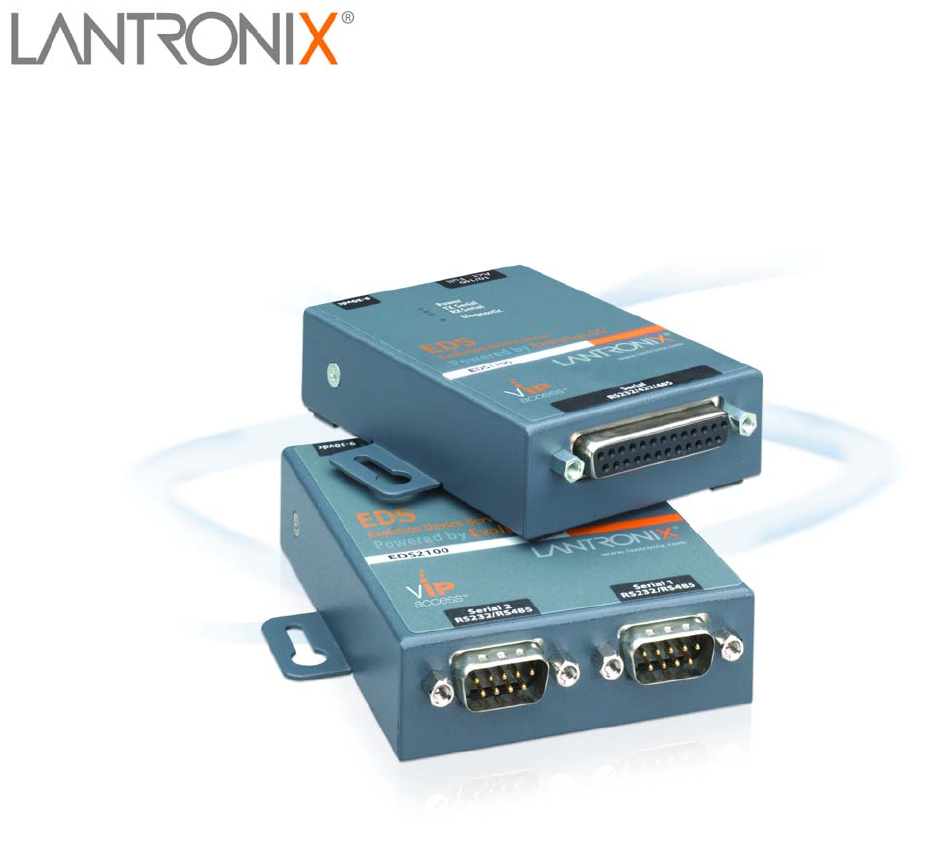
2: Overview The EDS1100/2100 Ethernet Device Server is a complete network-enabling solution. It empowers original equipment manufacturers (OEMs) to go to market quickly and easily with Ethernet networking and web page capabilities built into the products. The EDS1100 and EDS2100 provide the same solution and differ only in the number of serial ports. The EDS1100 has one serial port supported via a DB25 connector. The EDS2100 has two serial ports supported via 2 DB9 connectors.
2: Overview ATM machines Data display devices Modem Time/attendance clocks and terminals Protocol Support The EDS1100/2100 device server supports the following TCP/IP protocols: ARP, IP, UDP, TCP, ICMP, BOOTP, DHCP, Auto IP, Telnet, DNS, FTP, TFTP, HTTP/HTTPS, SSH, SSL/TLS, SNMP, SMTP, RSS, PPP and Syslog for network communications and management. TCP, UDP, TCP/AES, UDP/AES, Telnet, SSH and SSL/TLS for tunneling to the serial port.
2: Overview Command-Line Interface (CLI) Making the edge-to-enterprise vision a reality, the EDS1100/2100 with the Evolution OS™ uses industry-standard tools for configuration, communication, and control. For example, the Evolution OS™ uses a Command Line Interface (CLI) whose syntax is very similar to that used by data center equipment such as routers and hubs. VIP Access Virtual IP Access is the Lantronix technology that solves the access-through-firewall problem.
2: Overview You can use the EDS1100/2100 with the Lantronix Secure Com Port Redirector (SCPR) to encrypt COM port-based communications between PCs and virtually any electronic device. SCPR is a Windows application that creates a secure communications path over a network between the computer and serial-based devices that are traditionally controlled via a COM port.
2: Overview Addresses and Port Numbers Hardware Address The hardware address is also referred to as the Ethernet address or MAC address. The first three bytes of the Ethernet address are fixed and read 00-20-4A, identifying the unit as a Lantronix product. The fourth, fifth, and sixth bytes are unique numbers assigned to each unit. The following sample shows a hardware address: 00-20-4A-14-01-18 or 00:20:4A:14:01:18 IP Address Every device connected to an IP network must have a unique IP address.
3: Installation of EDS1100 This chapter describes how to install the EDS1100 device server.
3: Installation of EDS1100 Figure 3-2 shows the RS-232 pinout configuration. Figure 3-2 EDS1100 RS-232 Pinouts Figure 3-3 shows the RS-422 (4-wire) pinout configuration. Figure 3-3 EDS1100 RS-422 (4-wire) Pinouts Figure 3-3 shows the RS-485 (2-wire) pinout configuration.
3: Installation of EDS1100 Back Panel On the EDS1100 back panel, there is a power plug, reset button, and an RJ45 (10/100) Ethernet port as shown in Figure 3-5. Figure 3-5 EDS1100 Back Panel The Ethernet port has two LEDs that indicate the status of the connection.
3: Installation of EDS1100 Figure 3-6 Table 3-1 EDS1100 Top LEDs EDS1100 LEDs and Descriptions LED Description Power (blue) ON—EDS is receiving power TX Serial (green) Blinking—EDS is transmitting data on the serial port RX Serial (yellow) Blinking—EDS is receiving data on the serial port Diagnostic ON—EDS firmware has completed booting Blinking 1x/sec—EDS firmware is booting Blinking 2x/sec—EDS is writing a file to flash Blinking 4x/sec—EDS is compacting the file system Blinking 5x/sec—EDS is
3: Installation of EDS1100 2. Connect an Ethernet cable between the EDS1100 RJ45 port and your Ethernet network. 3. Plug the EDS1100 into the power outlet by using the power supply that was included in the packaging. The required input voltage is 9-30 VDC (center +) with 1.5W maximum power required. 4. Power up the serial device.
4: Installation of EDS2100 This chapter describes how to install the EDS2100 device server.
4: Installation of EDS2100 Figure 4-2 EDS2100 Pinout Configuration for RS-232 Figure 4-3 shows the pinout configuration for RS-422 (4-wire). Figure 4-3 EDS2100 Pinout Configuration for RS-422 (4-wire) Figure 4-4 shows the pinout configuration for RS-485 (2-wire). Figure 4-4 EDS2100 Pinout Configuration for RS-485 (2-wire) Back Panel On the EDS2100 back panel, there is a power plug, reset button, and an RJ45 (10/100) Ethernet port as shown in Figure 4-5.
4: Installation of EDS2100 The Ethernet port has two LEDs that indicate the status of the connection as follows: Left LED - Green ON 100Mbps Link - Green Blink 100Mbps Activity - Orange ON 10Mbps Link - Orange Blink 10Mbps Activity. Right LED - Green ON Full Duplex. - OFF Half Duplex The Ethernet port can connect to an Ethernet (10 Mbps) or Fast Ethernet (100 Mbps) network. Reset Button You can reset the EDS2100 to factory defaults, including clearing the network settings.
4: Installation of EDS2100 Table 4-1 EDS2100 LEDs and Descriptions (continued) LED Description TX Serial 2 (green) Blinking—EDS is transmitting data on serial port 2 RX Serial 2 (yellow) Blinking—EDS is receiving data on serial port 2 Diagnostic ON—EDS firmware has completed booting Blinking 1x/sec—EDS firmware is booting Blinking 2x/sec—EDS is writing a file to flash Blinking 4x/sec—EDS is compacting the file system Blinking 5x/sec— EDS is restoring factory defaults Installing the EDS2100 Be sur
4: Installation of EDS2100 Figure 4-7 EDS2100 Connections EDS1100/2100 User Guide 29
5: Using DeviceInstaller This chapter covers the steps for locating a EDS1100/2100 unit and viewing its properties and device details. It contains the following sections: Accessing EDS1100/2100 using DeviceInstaller Device Details Summary DeviceInstaller is a free utility program provided by Lantronix that discovers, configures, upgrades, and manages Lantronix Device Servers. It can be downloaded from the Lantronix website at www.lantronix.com/support/downloads.html.
5: Using DeviceInstaller Table 5-1 Current Settings and Description (continued) Current Settings Description Device Family Shows the EDS1100/2100 device family type as “EDS”. Type Shows the device type as either EDS1100 or 2100. ID Shows the EDS1100 or 2100 ID embedded within the unit. Hardware Address Shows the EDS1100/2100 hardware (MAC) address. Firmware Version Shows the firmware currently installed on the EDS1100/2100.
6: Configuration Using Web Manager This chapter describes how to configure the EDS1100/2100 by using Web Manager, the Lantronix browser-based configuration tool. The configuration is stored in nonvolatile memory and is retained without power. All changes take effect immediately, unless otherwise noted.
6: Configuration Using Web Manager Figure 6-1 Web Manager Home Page Web Manager Figure 6-2 shows the components of a typical Web Manager page.
6: Configuration Using Web Manager Figure 6-2 Components of a Typical Web Manager Page The Menu Bar (orange) always appears at the left side of the web page. There are accessible sections listed in the Main Menu, such as CLI, Diagnostics, Protocol Stack, etc. To display one of these sections, click it. The Help displays on the right side of the web page and contains information or instructions associated with the page.
6: Configuration Using Web Manager Note: There may be times when you must reboot the EDS1100/2100 for the new configuration settings to take effect. The chapters that follow indicate when a change requires a reboot. Table 6-3 Summary of Web Manager Pages Web Manager Page Description Page Status Shows product information and network, line, and tunneling settings. 33 CLI Shows Command Line Interface (CLI) statistics and lets you change the current CLI configuration settings.
6: Configuration Using Web Manager Table 6-3 Summary of Web Manager Pages (continued) Web Manager Page Description Page SSL Lets you upload an existing certificate or create a new self-signed certificate. 100 Syslog Lets you specify the severity of events to log and the server and ports to which the syslog should be sent. 80 System Lets you reboot the EDS1100/2100, restore factory defaults, upload new firmware, and change the EDS1100/2100 long and short names.
7: Network Settings This chapter describes how to access, view, and configure network settings from the Network web page. The Network web page contains sub-menus that enable you to view and configure the aspects of your network. This chapter contains the following sections: Network 1 Interface Status Network 1 Interface Configuration Network 1 Ethernet Link Network 1 Interface Status To view the Network 1 interface status, perform the following steps. 1. Click Network on the Main Menu.
7: Network Settings Network 1 Interface Configuration To configure the Network interface, perform the following steps. 1. Click Network on the Main Menu. 2. Click Network 1 > Interface > Configuration. Figure 7-2 shows the page that displays. Figure 7-2 Network 1 (eth0) Interface Configuration Web Page 3. Enter or modify the fields in Table 7-3. Table 7-3 Network 1 Interface Configuration Fields Field Description BOOTP Client Select On or Off.
7: Network Settings Table 7-3 Network 1 Interface Configuration Fields (continued) Field Description DHCP Client Select On or Off. At boot up the EDS1100/2100 will attempt to lease an IP address from a DHCP server and maintain the lease at regular intervals. Note: Overrides BOOTP, the configured IP address, network mask, gateway, hostname, and domain. IP Address Enter the EDS1100/2100 static IP address. You may enter it alone, in CIDR format, or with an explicit mask.
7: Network Settings 2. Click Network 1 > Link. Figure 7-4 shows the page that displays. Figure 7-4 Network1 (eth0) Ethernet Link Web Page 3. Enter or modify the fields in Table 7-5. Table 7-5 Network 1 (eth0) Ethernet Link Fields Field Description Speed Select the Ethernet link speed. Auto is the default. Duplex Select the Ethernet link duplex mode. Auto is the default. 4. Click Submit.
8: Line and Tunnel Settings This chapter describes how to view and configure lines and tunnels. It contains the following sections: Line Settings Tunnel Settings Line Settings You can view statistics and configure the serial interfaces (referred to as lines) by using the Line web page. When you click Line from the Main Menu, Line 1 fields display. To go to Line 2, click the Line 2 button. The following sub-menus you can use: Line Statistics—Displays statistics for the two lines.
8: Line and Tunnel Settings Figure 8-1 Line 1 Statistics Web Page Line Configuration To configure a line, perform the following steps. 1. Click Line > Line 1 > Configuration. Line 2 has the same fields as Line 1. Figure 8-2 shows the page that displays.
8: Line and Tunnel Settings Figure 8-2 Line 1 Configuration Web Page 2. Enter or modify the fields in Table 8-3. Table 8-3 Line 1 Configuration Fields Field Description Name Enter a name for the line. Interface Select the interface type from the drop-down menu. The default is RS232. State Indicates whether the current line is enabled. To change the status, select Enabled or Disabled from the drop-down menu. Protocol Select the protocol from the drop-down menu. The default is Tunnel.
8: Line and Tunnel Settings Table 8-3 Line 1 Configuration Fields (continued) Field Description Flow Control Select the flow control from the drop-down menu. The default is None. Xon Char Specify the character to use to start the flow of data when Flow Control is set to Software. Prefix a decimal character with \ or a hexadecimal character with 0x, or provide a single printable character. The default Xon char is 0x11.
8: Line and Tunnel Settings Figure 8-4 Line 1 Command Mode Web Page 2. Enter or modify the fields in Table 8-5. Table 8-5 Line 1 Command Mode Fields Field Description Mode Select the method of enabling Command Mode or choose to disable Command Mode. Always—Immediately enables Command Mode for the serial line. Use Serial String—Enables Command Mode when the serial string is read on the serial line during boot time. Disabled—Turns off Command Mode.
8: Line and Tunnel Settings Table 8-5 Line 1 Command Mode Fields (continued) Field Description Echo Serial String Select Yes to enable echoing of the serial string at boot-up. Signon Message Enter the boot-up signon message. Select a string type. Text—String of bytes sent on the serial line during boot time. Binary—One or more byte values separated by commas. Each byte value may be decimal or hexadecimal. Start hexadecimal values with 0x.
8: Line and Tunnel Settings Tunnel Statistics The EDS1100/2100 logs tunneling statistics. The Dropped statistic shows connections ended by the remote location. The Disconnects statistic shows connections ended by the EDS1100/2100. To display the tunnel statistics, perform the following steps. 1. Click Tunnel on the Main Menu. Figure 8-6 shows the page that displays. Figure 8-6 Tunnel 1 Statistics Web Page Serial Settings Serial line settings are configurable for both serial line 1 and serial line 2.
8: Line and Tunnel Settings Figure 8-7 Tunnel 1 Serial Settings Web Page 2. View or modify the fields in Table 8-8. Table 8-8 Tunnel 1 Serial Settings Fields Fields Description Line Settings Display only field. Current serial settings for the line. Protocol Display only field. The protocol being used for the tunnel. Buffer Size Enter the buffer size used for the tunneling of serial data received. Requires reboot to take effect. DTR Select when to assert DTR.
8: Line and Tunnel Settings 3. Click Submit. Packing Mode Packing Mode takes data from the serial port, packs it together, and sends over the network. Packing can be configured based on threshold (size in bytes) or timeout (milliseconds). Size is set by modifying the threshold field. When the number of bytes exceeds the threshold, a packet is sent. The timeout field is used to force a packet to be sent after a maximum time. The packet is sent even if the threshold maximum is not reached.
8: Line and Tunnel Settings Figure 8-10 Tunnel 1 Packing Mode (Timeout) 3. Enter or modify the fields in Table 8-11. Table 8-11 Tunnel Packing Mode (Timeout) Fields Field Description Threshold Send the queued data when the number of queued bytes reaches the threshold. Timeout Enter a time, in milliseconds, for the EDS1100/2100 to send the queued data after the first character was received. 4. Click Submit. 5. Click Send Character. Figure 8-12 shows the page that displays.
8: Line and Tunnel Settings Figure 8-12 Tunnel 1 Packing Mode (Send Character) 6. Enter or modify the fields in Table 8-13. Table 8-13 Tunnel Packing Mode (Send Character) Fields Field Description Threshold Send the queued data when the number of queued bytes reaches the threshold. Send Character Enter the send character. Upon receiving this character, the EDS1100/2100 sends out the queued data. Trailing Character Enter the trailing character.
8: Line and Tunnel Settings Accept Mode supports the following protocols: SSH (EDS1100/2100 acts as the server). When using SSH, the SSH server host keys and at least one SSH authorized user must be configured. SSL TCP AES encryption over TCP Telnet (EDS1100/2100 supports IAC codes. It drops the IAC codes when Telnetting and does not forward them to the serial port).
8: Line and Tunnel Settings Figure 8-14 Tunnel 1 Accept Mode Web Page 2. Enter or modify the fields in Table 8-15. Table 8-15 Tunnel Accept Mode Fields Field Description Mode Select the method used to start a tunnel in Accept mode. Choices are: EDS1100/2100 User Guide Disabled—Do not accept an incoming connection. Always—Accept an incoming connection. (default) Any Character—Start waiting for an incoming connection when any character is read on the serial line.
8: Line and Tunnel Settings Table 8-15 Tunnel Accept Mode Fields (continued) Field Description Local Port Enter the port number for use as the local port. The defaults are port 10001 for Tunnel 1 and port 10002 for Tunnel 2. Protocol Select the protocol type for use with Accept Mode. The default protocol is TCP. If you select TCP AES you will need to configure the AES keys.
8: Line and Tunnel Settings UDP (available only in Connect Mode because it is a connectionless protocol). Telnet Note: The Local Port in Connect Mode is independent of the port configured in Accept Mode.
8: Line and Tunnel Settings 2. Enter or modify the fields in Table 8-17. Table 8-17 Tunnel Connect Mode Fields Field Description Mode Select the method to be used to attempt a connection to a remote host or device. Choices are: Always—A connection is attempted until one is made. If the connection gets disconnected, the EDS1100/2100 retries until it makes a connection. (default) Disable—An outgoing connection is never attempted.
8: Line and Tunnel Settings Table 8-17 Tunnel Connect Mode Fields (continued) Field Description Host Click in the Host field to configure the Host parameters and enter the following fields: VIP—Enabling the VIP directs the tunnel to connect to a remote Lantronix Virtual IP identified by the VIP Name. When VIP is enabled, the Host 2 field displays. See 12: VIP for more information. Default is Disabled. Note: The EDS1100/2100 supports configuration of up to sixteen hosts.
8: Line and Tunnel Settings Table 8-17 Tunnel Connect Mode Fields (continued) Field Description Reconnect Timer Enter the reconnect time in milliseconds. The EDS1100/2100 attempts to reconnect after the specified amount of time when a connection fails or when exiting an established connection. This behavior depends upon the Disconnect Mode.
8: Line and Tunnel Settings Figure 8-18 Host Mode Host Mode controls how multiple hosts operate in Connect Mode. The following options are available: Sequential—A Tunnel to the first host is attempted. If the connection fails, the next host specified is attempted. This will continue until a connection is made. If a connection is dropped after a successful connection has been established, tunnel connection attempts begin again from the first host.This is the default.
8: Line and Tunnel Settings Figure 8-19 Host 2 Configuration Fields 2. Enable VIP by clicking Enabled. The default is disabled. 3. Enter a VIP Name. Note: See 12: VIP for more information about specifying VIP names. 4. Enter the Port number. 5. Select the Protocol from the pull-down menu. Depending upon the specified protocol, other options are as follows: For TCP and Telnet, input the keep alive milliseconds. For SSH, input the SSH username.
8: Line and Tunnel Settings Host List Promotion The EDS1100/2100 allows the host list connection order to be specified. There are two types of host modes: Sequential and Simultaneous. Simultaneous connections occur approximately at the same time to all listed hosts. Sequential host lists establish a prioritized list of tunnels. The host specified as Host 1 will be attempted first. If that fails, it will proceed to Host 2, 3, etc, in the order they are specified.
8: Line and Tunnel Settings Timeout period elapsed and no activity. Both Accept Mode and Connect Mode must be idle for a specified time frame. Modem control inactive setting. Note: To clear data out of the serial buffers upon a disconnect, enable “Flush Serial Data”. To configure Disconnect Mode, perform the following steps. 1. Click Tunnel 1 > Disconnect Mode. Figure 8-21 shows the page that displays. Figure 8-21 Tunnel 1 Disconnect Mode Web Page 2. Enter or modify the fields in Table 8-22.
8: Line and Tunnel Settings Table 8-22 Tunnel Disconnect Mode Fields (continued) Field Description Timeout Enter a time, in milliseconds, for the EDS1100/2100 to disconnect on a timeout. The value 0 (zero) disables the idle timeout. Flush Serial Data Select Enabled to flush the serial data buffer on a disconnection. 3. Click Submit. Modem Emulation The EDS1100/2100 supports Modem Emulation mode for devices that send out modem signals.
8: Line and Tunnel Settings Table 8-1 Modem Emulation Commands and Descriptions (continued) Command Description ATEn Switches echo in Command Mode (off - 0, on - 1). ATH Disconnects the network session. ATI Shows modem information. ATQn Quiet mode (0 - enable results code, 1 - disable results code.) ATVn Verbose mode (0 - numeric result codes, 1 - text result codes.) ATXn Command does nothing and returns OK status. ATUn Accept unknown commands. (n value of 0 = off. n value of 1 = on.
8: Line and Tunnel Settings Figure 8-23 Tunnel 1 Modem Emulation Web Page 2. Enter or modify the fields in Table 8-24. Table 8-24 Tunnel Modem Emulation Fields Field Description Echo Pluses Select On to echo +++ when entering modem Command Mode. Echo Commands Select On to echo the modem commands to the console. Verbose Response Select On to send modem response codes out on the serial line. Response Type Select the type of response code: Text or Numeric.
8: Line and Tunnel Settings Table 8-24 Tunnel Modem Emulation Fields (continued) Field Description Connect String Enter the connect string. This modem initialization string prepares the modem for communications. It is a customized string sent with the “CONNECT” modem response code. Display Remote IP Selects whether the incoming RING sent on the Serial Line is followed by the IP address of the caller. Default is Disabled. 3. Click Submit.
9: Terminal and Host Settings This chapter describes how to view and configure terminals and hosts. It contains the following sections: Terminal Settings Host Configuration Terminal Settings You can configure a terminal on a serial line or on the network by using the Terminal web page. When you click Terminal from the Main Menu, Line 1 fields display. To go to the network or line 2, click the Network or Line 2 button.
9: Terminal and Host Settings 2. Enter or modify the fields in Table 9-2. Table 9-2 Terminal on Network Configuration Fields Field Description Terminal Type Enter text to describe the type of terminal. The text will be sent to a host via interpret as command (IAC). Note: IAC is a method to send commands over the network such as send break or start echoing. Login Connect Menu Select the interface to display when the user logs in. Choices are: Enabled = shows the Login Connect Menu.
9: Terminal and Host Settings Figure 9-3 Terminal on Line 1 Configuration Web Page Enter or modify the fields in Table 9-4. Table 9-4 Terminal on Line 1 Configuration Fields Field Description Terminal Type Enter text to describe the type of terminal. The text will be sent to a host via interpret as command (IAC). Note: IAC is a method to send commands over the network such as send break or start echoing.
9: Terminal and Host Settings Table 9-4 Terminal on Line 1 Configuration Fields (continued) Field Description Send Break Enter a Send Break control character, e.g., Y, or blank to disable. When the Send Break control character is received from the network on its way to the serial line, it is not sent to the line; instead, the line output is forced to be inactive (the break condition). Break Duration Enter how long the break should last in milliseconds.
9: Terminal and Host Settings 2. Enter or modify the fields in Table 9-6. Table 9-6 Host Configuration Fields Field Description Name Enter a name for the host. This name appears on the Login Connect Menu. To leave a host out of the menu, leave this field blank. Protocol Select the protocol to use to connect to the host. Choices are: Telnet SSH Note: SSH keys must be loaded or created on the SSH page for the SSH protocol to work. SSH Username Appears if you selected SSH as the protocol.
10: Services Settings This chapter describes the available services and how to configure each. It contains the following sections: DNS Status and Cache PPP Configuration SNMP Configuration FTP TFTP Syslog HTTP RSS LPD DNS Status and Cache The primary and secondary domain name system (DNS) addresses come from the active interface. The static addresses displayed on the Network Interface Configuration web page may be overridden by DHCP or BOOTP.
10: Services Settings Figure 10-1 DNS Status and Cache Web Page PPP Configuration The Point-to-Point Protocol (PPP) establishes a direct connection between two nodes. It defines a method for data link connectivity between devices using physical layers (such as serial lines). The EDS1100/2100 supports two types of PPP authentication: Password Authentication Protocol (PAP) and Challenge Handshake Authentication Protocol (CHAP).
10: Services Settings The EDS1100/2100 also supports authentication scheme of “None” when no authentication is required during link negotiation. Since the EDS1100/2100 does not support Network Address and Port Translation (NAPT), static routing table entries must be added to the serial-side and network-side devices (both of which are external devices). Use the EDS1100/2100 Web Manager or CLI to configure a network link using PPP over a serial line.
10: Services Settings 2. Enter or modify the fields in Table 10-1. Table 10-1 PPP Configuration Fields Field Description Local IP Address Enter the IP address assigned to the EDS1100/2100’s PPP interface. Peer IP Address Enter the IP address assigned to the peer (when requested during negotiation). Authentication Mode Choose the authentication mode: None—No authentication is required. PAP—Password Authentication Protocol. CHAP—Challenge Handshake Authentication Protocol. 3.
10: Services Settings Figure 10-3 SNMP Web Page 2. Enter or modify the fields in Table 10-2. Table 10-2 SNMP Fields Field Description SNMP Agent Select On to enable SNMP. Read Community Enter the SNMP read-only community string. Write Community Enter the SNMP read/write community string. System Contact Enter the name of the system contact. System Name Enter the system name. System Description Enter the system description. System Location Enter the system location.
10: Services Settings Table 10-2 SNMP Fields (continued) Field Description Primary Trap Dest IP Enter the primary SNMP trap host. Secondary Trap Dest IP Enter the secondary SNMP trap host. 3. Click Submit. Note: You can delete the read and write communities, and system name by clicking the [Delete] link in the Current Configuration table. FTP The FTP web page shows the FTP configuration and statistics about the FTP server. To configure FTP, perform the following steps. 1.
10: Services Settings 2. Enter or modify the fields in Table 10-3. Table 10-3 FTP Fields Field Description State Select Enabled to enable the FTP server. Admin Username Enter the username to use when logging in via FTP. Admin Password Enter the password to use when logging in via FTP. 3. Click Submit. TFTP In the TFTP web page, you can configure the server, and view the status and statistics. To configure TFTP server, perform the following steps. 1. Click TFTP on the Main Menu.
10: Services Settings 2. Enter or modify the fields in Table 10-4. Table 10-4 TFTP Server Fields Field Description State Select Enabled to enable the TFTP server. Allow TFTP File Creation Select whether to allow the creation of new files stored on the TFTP server. Allow Firmware Update Specifies whether or not the TFTP Server is allowed to accept a firmware update for the device. An attempt to update firmware is recognized based on the name of the file.
10: Services Settings Figure 10-6 Syslog Web Page 2. Enter or modify the fields in Table 10-5 Table 10-5 Syslog Fields Field Description State Select to enable or disable the syslog. Host Enter the IP address of the remote server to which system logs are sent for storage. Local Port Enter the number of the local port on the EDS1100/2100 from which system logs are sent. Remote Port Enter the number of the port on the remote server that supports logging services. The default is 514.
10: Services Settings HTTP HyperText Transfer Protocol (HTTP) is an application layer standard for Internet documents. HTTP defines how messages get formatted and transmitted. It also defines the actions web servers and browsers should take in response to different commands. HTTP Authentication enables the requirement of usernames and passwords for access to the EDS1100/2100 device.
10: Services Settings Note: The HTTP log is a scrolling log, with the last Max Log Entries cached and viewable. You can change the maximum number of entries that can be viewed on the HTTP Configuration Web Page. HTTP Configuration To configure HTTP, perform the following steps. 1. Click HTTP > Configuration. Figure 10-8 shows the page that displays. Figure 10-8 HTTP Configuration Web Page 2. Enter or modify the fields in Table 10-6.
10: Services Settings Table 10-6 HTTP Configuration Fields (continued) Field Description HTTP Port Enter the port for the HTTP server to use. The default is 80. HTTPS Port Enter the port for the HTTPS server to use. The default is 443. The HTTP server only listens on the HTTPS Port when an SSL certificate is configured. HTTPS Protocols Select to enable or disable the following protocols: SSL3 = Secure Sockets Layer version 3 TLS1.0 = Transport Layer Security version 1.0. TLS 1.
10: Services Settings HTTP Authentication To configure HTTP authentication, perform the following steps. 1. Click HTTP > Authentication. Figure 10-9 shows the page that displays. Figure 10-9 HTTP Authentication Web Page 2. Enter or modify the fields in Table 10-7. Table 10-7 HTTP Authentication Fields Fields Description URI Enter the Uniform Resource Identifier (URI). Note: Realm EDS1100/2100 User Guide The URI must begin with ‘/’ to refer to the filesystem.
10: Services Settings Table 10-7 HTTP Authentication Fields (continued) Fields Description Auth Type Select the authentication type: Username None—No authentication is necessary. Basic—Encodes passwords using Base64. Digest—Encodes passwords using MD5. SSL—The page can only be accessed over SSL (no password is required). SSL/Basic—The page is accessible only over SSL and encodes passwords using Base64.
10: Services Settings Figure 10-10 RSS Web Page 2. Enter or modify the fields in Table 10-8. Table 10-8 RSS Fields Fields Description RSS Feed Select On to enable RSS feeds to an RSS publisher. Persistent Select On to enable the RSS feed to be written to a file (cfg_log.txt) and to be available across reboots. Max Entries Sets the maximum number of log entries. Only the last Max Entries are cached and viewable. 3. Click Submit.
10: Services Settings LPD The EDS1100/2100 acts as a print server if a printer gets connected to one of its serial ports. Clicking the Line Printer Daemon (LPD) link in the Main Menu displays the LPD web page. The LPD web page has three sub-menus for viewing print queue statistics, changing print queue configuration, and printing a test page. Because the LPD lines operate independently, you can specify different configuration settings for each.
10: Services Settings Figure 10-12 LPD Configuration Web Page 2. Enter or modify the fields in Table 10-9. Table 10-9 LPD Configuration Fields Field Description Banner Select Enabled to print the banner even if the print job does not specify to do so. Selected by default. Binary Select Enabled for the EDS1100/2100 to pass the entire file to the printer unchanged. Otherwise, the EDS1100/2100 passes only valid ASCII and valid control characters to the printer.
10: Services Settings Table 10-9 LPD Configuration Fields (continued) Field Description Convert Newlines Select Enabled to convert single newlines and carriage returns to DOS-style line endings. SOJ String If Start of Job (above) is enabled, enter the string to be sent to the printer at the beginning of a print job. The limit is 100 characters. Indicate whether the string is in text or binary format. EOJ String If End of Job (above) is enabled, enter the string to send at the end of a print job.
11: Security Settings The EDS1100/2100 supports Secure Shell (SSH) and Secure Sockets Layer (SSL). SSH is a network protocol for securely accessing a remote device. SSH provides a secure, encrypted communication channel between two hosts over a network. It provides authentication and message integrity services. Secure Sockets Layer (SSL) is a protocol that manages data transmissiong security over the Internet.
11: Security Settings Figure 11-1 SSH Server Host Keys Web Page 2. Enter or modify the fields in Table 11-1. Table 11-1 SSH Server Host Keys Fields Field Description Upload Keys Private Key—Enter the path and name of the existing private key you want to upload or use the Browse button to select the key. Be sure the private key will not be compromised in transit.
11: Security Settings Table 11-1 SSH Server Host Keys Fields (continued) Field Description Create New Keys Key Type—Select a key type to use for the new key. RSA = use this key with the SSH1 and SSH2 protocols. DSA = use this key with the SSH2 protocol. Bit Size—Select a bit length for the new key: 512, 768, 1024. Using a larger bit size takes more time to generate the key.
11: Security Settings Figure 11-2 SSH Server Authorized Users Web Page 2. Enter or modify the fields in Table 11-2. Table 11-2 SSH Server Authorized Users Fields Field Description Username Enter the name of the user authorized to access the SSH server. Password Enter the password associated with the username. Public RSA Key Enter the path and name of the existing public RSA key you want to use with this user or use the Browse button to select the key.
11: Security Settings SSH Client Known Hosts You can change SSH client settings for known hosts. You do not have to complete the fields on this page for communication to occur. However, adding information in the fields adds another layer of security that protects against Man-In-The-Middle (MITM) attacks. To configure the SSH client for known hosts, perform the following steps. 1. Click SSH > Client Known Hosts. Figure 11-3 shows the page that displays. Figure 11-3 SSH Client Known Hosts Web Page 2.
11: Security Settings Table 11-3 SSH Client Known Hosts Fields (continued) Public DSA Key Enter the path and name of the existing public DSA key you want to use with this known host or use the Browse button to select the key. 3. Click Submit. Note: You can delete stored settings when the [Delete] link displays in the Current Configuration table. SSH Client User Configuration You can configure SSH client settings for users.
11: Security Settings Figure 11-4 SSH Client Users Web Page 2. Enter or modify the fields in Table 11-4. Table 11-4 SSH Client Users Fields Field Description Username Enter the name that the EDS1100/2100 uses to connect to a SSH server. Password Enter the password associated with the username. Remote Command Enter the command that can be executed remotely. Default is shell, which tells the SSH server to execute a remote shell upon connection.
11: Security Settings Table 11-4 SSH Client Users Fields (continued) Field Description Create New Keys Username—Enter the name of the user associated with the new key. Key Type—Select the key type to be used for the new key. Choices are: RSA—Use this key with the SSH1 and SSH2 protocols. DSA—Use this key with the SSH2 protocol. Bit Size—Select the bit length of the new key: - 512 - 768 - 1024 Note: Using a larger Bit Size takes more time to generate the key.
11: Security Settings Whichever side is acting as server decides which cipher suite to use for a connection. It is usually the strongest common denominator of the cipher suite lists supported by both sides. SSL Certificates The goal of a certificate is to authenticate its sender. It is analogous to a paper document that contains personal identification information and is signed by an authority, for example a notary or government agency.
11: Security Settings Certificates and private keys can be stored in several file formats. Best known are PKCS12, DER and PEM. Certificate and key can be in the same file or in separate files. The key can be encrypted with a password or not. The EDS1100/2100 currently only accepts separate PEM files. The key needs to be unencrypted. SSL Utilities Several utilities exist to convert between the formats as follows: OpenSSL—Open source set of SSL related command line utilities.
11: Security Settings Figure 11-5 SSL Web Page EDS1100/2100 User Guide 100
11: Security Settings 2. Enter or modify the fields in Table 11-5. Table 11-5 SSL Fields Field Description Upload Certificate New Certificate—This certificate identifies the EDS1100/2100 to peers. It is used for HTTPS and SSL Tunneling. Enter the path and name of the certificate you want to upload, or use the Browse button to select the certificate. RSA or DSA certificates with 512 to 1024 bit public keys are allowed. Note: The file format must be PEM.
11: Security Settings Table 11-5 SSL Fields (continued) Field Description Expires—Enter the expiration date, in mm/dd/yyyy format, for the new selfsigned certificate. Example: An expiration date of May 9, 2010 is entered as 05/09/2010. Key Length—Select the bit size of the new self-signed certificate. Choices are: 512 bits 768 bits 1024 bits The larger the bit size, the longer it takes to generate the key.
12: VIP VIP (Virtual IP) takes advantage of the Lantronix ManageLinx technology that solves the accessthrough-firewall problem. ManageLinx utilizes existing network infrastructure to create a virtual device network (VDN). VDN provides direct access to only authorized equipment, behind firewalls, from anywhere via the net. The VDN technology enables you to create dedicated TCP/IP connections between any two devices, using easily deployed hardware appliances. There is no client software to install.
12: VIP Enable VIP Once the bootstrap file has been imported, VIP Access can be enabled and a conduit with the DSM will be established. The VIP Statistics shows the current state of the conduit. When configured correctly, a conduit with the DSM will be maintained at all times. Configure Tunnels to Use VIP Configuring Connect Mode tunnels to use VIP is a simple matter of configuring a tunnel as is normally done, but also enabling VIP in the Tunnel Host settings, and using a VIP Name for the address.
12: VIP 2. Enter or modify the fields in Table 12-1. Table 12-1 VIP Statistics Fields Field Description DSM IP Address Address of the Device Services Manager (DSM) from the bootstrap file. Local DNA ID Identity of this device from the bootstrap file. Tunnel User username of this device from the bootstrap file. Tunnel Port List DSM listening ports from the bootstrap file. Current Tunnel Port DSM port currently used by the conduit.
12: VIP Figure 12-2 VIP Configuration Web Page 2. Click Enabled to use VIP addresses in Tunnel Accept Mode and Tunnel Connect Mode. The default is disabled. 3. Click Submit.
13: Maintenance and Diagnostics Settings This chapter describes maintenance and diagnostic methods and contains the following sections: Filesystem Protocol Stack IP Address Filter Query Port Diagnostics System Filesystem The EDS1100/2100 uses a flash filesystem to store files. You can view file diagnostics and/or modify files. There are two subsections: Statistics and Browse.
13: Maintenance and Diagnostics Settings Figure 13-1 Filesystem Statistics Web Page 2. Click Compact in the Actions row to compact the files. Note: The compact should not be needed under normal circumstances as the system manages this automatically. 3. Back up all files before you perform Step 4, because all user files get erased in that step. 4. Cick Format in the Actions row. The configuration gets retained. Filesystem Browser To browse the filesystem, perform the following steps. 1.
13: Maintenance and Diagnostics Settings Figure 13-2 Filesystem Browser Web Page 2. Click a filename to view the contents.
13: Maintenance and Diagnostics Settings 3. Click the X next to a filename to delete the file and then you can delete the directory. The directory has to be empty before you can delete it. Note: Changes apply to the current directory view. To make changes within other folders, click the folder or directory and then enter the parameters in the settings listed in Table 13-1. Files can be copied or moved by using the fields noted in Table 13-1.
13: Maintenance and Diagnostics Settings Protocol Stack In the Protocol Stack web page, you can configure TCP, IP, ICMP, and ARP. TCP To configure the network protocols, perform the following steps. 1. Click Protocol Stack on the Main Menu. TCP is the default. Figure 13-3 shows the page that displays. Figure 13-3 TCP Web Page 2. Enter or modify the fields in Table 13-2. Table 13-2 TCP Fields Field Description Send RSTs Click Enabled to send RSTs or Disabled to stop sending RSTs.
13: Maintenance and Diagnostics Settings Table 13-2 TCP Fields (continued) Field Description Ack Limit Enter a number to limit how many packets get received before an ACK gets forced. If there is a large amount of data to acknowledge, an ACK gets forced. If the sender TCP implementation waits for an ACK before sending more data even though the window is open, setting the Ack Limit to 1 packet improves performance by forcing immediate acknowledgements.
13: Maintenance and Diagnostics Settings 3. Click Submit. ICMP To set the ICMP, perform the following steps. 1. Click Protocol Stack < ICMP. Figure 13-5 shows the page that displays. Figure 13-5 ICMP Web Page 2. Click Enabled. 3. Click Submit. ARP 1. Click Protocol Stack > ARP. Figure 13-6 shows the page that displays.
13: Maintenance and Diagnostics Settings Figure 13-6 ARP Web Page 1. Enter the fields in Table 13-3. Table 13-3 ARP Web Page Fields Field Description ARP Timeout Enter hours, minutes and seconds. This is the maximum duration an address remains in the cache. IP Address Enter the IP address for the ARP cache. MAC Address Enter the MAC address to add to the ARP cache. Current State [Remove All] Removes all entries in the ARP cache or click [Remove] in the specific table entry to remove that entry.
13: Maintenance and Diagnostics Settings IP Address Filter The IP address filter allows specified hosts and subnets to communicate with the EDS1100/2100. Note: If using DHCP/BOOTP, ensure the DHCP/BOOTP server IP address is in the list. To configure the IP address filter, perform the following steps. 1. Click the IP Address Filter on the Main Menu. Figure 13-7 shows the page that displays. Figure 13-7 IP Address Filter Web Page Note: Be aware not to assign your network IP address as “filtered.
13: Maintenance and Diagnostics Settings 3. Click Add. Note: You can remove IP addresses by clicking [Remove] in the Current State table. Query Port The query port (0x77FE) is used for the automatic discovery of the device by the DeviceInstaller utility. Only 0x77FE discover messages from DeviceInstaller are supported. For more information on DeviceInstaller, see 5: Using DeviceInstaller To configure the query port server, perform the following steps. 1. Click Query Port on the Main Menu.
13: Maintenance and Diagnostics Settings Diagnostics The EDS1100/2100 has several tools to perform diagnostics and view device statistics. These include information on: Hardware MIB-II IP Sockets Ping Traceroute DNS Lookup Memory Buffer Pools Processes Hardware To display the Hardware configuration, perform the following steps. 1. Click Diagnostics > Hardware. Figure 13-9 shows the page that displays.
13: Maintenance and Diagnostics Settings Figure 13-9 Hardware Web Page MIB-II The MIB-II Network Statistics page shows the available SNMP MIBs. To display MIB-II statistics, perform the following steps. 1. Click Diagnostics > MIB-II at the top of the page. Figure 13-10 shows the page that displays.
13: Maintenance and Diagnostics Settings Figure 13-10 MIB-II Web Page 2. Click any of the links to open the corresponding table and statistics. Note: For more information, refer to the following Requests for Comments (RFCs): RFC 1213—MIB-II definitions. RFC 2011—Updated definitions for IP and ICMP. RFC 2012—Updated definitions for TCP. RFC 2013—Updated definitions for UDP. RFC 2096—Definitions for IP forwarding. IP Sockets To display all open IP sockets, perform the following steps.
13: Maintenance and Diagnostics Settings Figure 13-11 IP Sockets Web Page Ping To ping a remote device or computer, perform the following steps. 1. Click Diagnostics > Ping. Figure 13-12 shows the page that displays.
13: Maintenance and Diagnostics Settings Figure 13-12 Ping Web Page 2. Enter or modify the fields in Table 13-5. Table 13-5 Ping Fields Field Description Host Enter the IP address or host name for the EDS1100/2100 to ping. Count Enter the number of ping packets EDS1100/2100 should attempt to send to the Host. The default is 3. Timeout Enter the time, in seconds, for the EDS1100/2100 to wait for a response from the host before timing out. The default is 5 seconds. 3. Click Submit.
13: Maintenance and Diagnostics Settings Figure 13-13 Traceroute Web Page 2. Enter or modify the fields in Table 13-6. Table 13-6 Traceroute Fields Field Description Host Enter the IP address or DNS hostname. This address is used to show the path between it and the EDS1100/2100 when issuing the traceroute command. Count Enter the number of ping packets EDS1100/2100 should attempt to send to the Host. The default is 3 attempts.
13: Maintenance and Diagnostics Settings To use forward or reverse DNS lookup, perform the following steps. 1. Click Diagnostics < DNS Lookup. Figure 13-14 shows the page that displays. Figure 13-14 DNS Lookup Web Page 2. Enter or modify the fields in Table 13-7. Table 13-7 DNS Lookup Fields Field Description Host Perform one of the following: For reverse lookup to locate the hostname for that IP address, enter an IP address.
13: Maintenance and Diagnostics Settings Memory The Memory web page displays total and available memory in bytes, along with the number of fragments, allocated blocks, and memory status.To display memory statistics, perform the following steps. 1. Click Diagnostics > Memory. Figure 13-15 shows the page that displays. Figure 13-15 Memory Web Page Buffer Pools Private buffer pools ensure deterministic memory management. To display the buffer pools, perform the following steps. 1.
13: Maintenance and Diagnostics Settings Figure 13-16 Buffer Pools Web Page Processes The Processes web page shows all the processes currently running on the system. It shows the Process ID (PID), the percentage of total CPU cycles a process used within the last three seconds, the total stack space available, the maximum amount of stack space used by the process since it started, and the process name. To display the processes, perform the following steps. 1. Click Diagnostics > Processes.
13: Maintenance and Diagnostics Settings Figure 13-17 Processes Web Page Note: The Adobe SVG plug-in is required to view the CPU Load Graph.
13: Maintenance and Diagnostics Settings System The System web page enables the rebooting of the device, restoring factory defaults, uploading new firmware, specifying the short and long name, and viewing the current system configuration. To configure system settings, perform the following steps. 1. Click System on the Main Menu. Figure 13-18 shows the page that displays. Figure 13-18 System Web Page 2. Enter or modify the fields in Table 13-8.
13: Maintenance and Diagnostics Settings Table 13-8 System Fields (continued) Field Description Restore Factory Defaults Click Factory Defaults to restore the EDS1100/2100 to the original factory settings. All configurations will be lost. The EDS1100/2100 automatically reboots upon setting back to the defaults. Upload New Firmware Click Browse to locate the firmware file location. Click Upload to install the firmware on the EDS1100/2100.
14: Advanced Settings This chapter describes advanced configuration of Email, CLI, and XML. It contains the following sections: Email Statistics Email Configuration Command Line Interface XML Configuration Email Statistics The Email Statistics web page displays when you click Email from the Main Menu. It shows statistics and current usage information about the email subsystem.
14: Advanced Settings 2. Click the Log [Clear] link to clear the log. Email Configuration The EDS1100/2100 allows you to view and configure email alerts relating to the events occurring within the system. To configure email settings, perform the following steps. 1. Click Email > Email 1 > Configuration. Figure 14-2 shows the page that displays.
14: Advanced Settings 2. Enter or modify the fields in Table 14-1. Table 14-1 Email 1 Configuration Fields Field Description To Enter the email address to which the email alerts will be sent. Multiple addresses are separated by semicolon (;). Cc Enter the email address to which the email alerts will be copied. Multiple addresses are separated by semicolon (;). From Enter the email address to list in the From field of the email alert.
14: Advanced Settings Figure 14-3 CLI Statistics Web Page CLI Configuration To configure the CLI, perform the following steps. 1. Click CLI > Configuration. Figure 14-4 shows the page that displays.
14: Advanced Settings Figure 14-4 CLI Configuration Web Page 2. Enter or modify the fields in Table 14-2. Table 14-2 CLI Configuration Fields Field Description Login Password Enter the password for Telnet access. Enable Level Password Enter the password for access to the Command Mode Enable level. There is no password by default. Quit connect line Enter a string to terminate a connect line session and resume the CLI.
14: Advanced Settings Table 14-2 CLI Configuration Fields (continued) Field Description SSH State Select On to enable SSH access. SSH is enabled by default. SSH Port Enter the SSH port to use for SSH access. The default is 22. SSH Max Sessions Maximum number of simultaneous SSH sessions. 3. Click Submit. XML Configuration The EDS1100/2100 enables configuration of devices by using XML configuration records (XCRs).
14: Advanced Settings XML Export Configuration To export a system configuration record, perform the following steps. 1. Click XML on the Main Menu. Figure 14-5 shows the page that displays. Figure 14-5 XML Export Configuration Web Page 2. Enter or modify the fields in Table 14-3: Table 14-3 XML Export Configuration Fields Field Description Export to browser Select this option to export the XCR data in the selected fields to a web browser.
14: Advanced Settings Table 14-3 XML Export Configuration Fields (continued) Field Description Export to local file Select this option to export the XCR data to a file on the device. If you select this option, enter a file name for the XML configuration record. Export secrets Only use this with extreme caution. If selected, secret password and key information will be exported. Use only with a secure link, and save only in secure locations.
14: Advanced Settings Figure 14-6 XML Export Status Web Page 2. Enter or modify the fields in Table 14-4. Table 14-4 XML Export Status Fields Field Description Export to browser Select this option to export the XML status record to a web browser. Export to local file Select this option to export the XML status record to a file on the device. If you select this option, enter a file name for the XML status record.
14: Advanced Settings Import Configuration To import a system configuration, perform the following steps. 1. Click XML > Import Configuration. Figure 14-7 shows the page that displays. Figure 14-7 Import Configuration Web Page 2. Click Configuration from External file. Figure 14-8 shows the page that displays.
14: Advanced Settings Figure 14-8 Import Configuration from External File Web Page 3. Enter the path and file name of the external XCR file you want to import or browse to select the XCR file. 4. Go back to the Import Configuration web page. 5. Click Configuration from Filesystem. Figure 14-9 shows the page that displays.
14: Advanced Settings Figure 14-9 Import Configuration from Filesystem Web Page 6. Enter the fields shown in Table 14-5. Table 14-5 Import Configuration from Filesystem Fields Field Description Filename Enter the name of the file on the EDS1100/2100 (local to its filesystem) that contains XCR data.
14: Advanced Settings Table 14-5 Import Configuration from Filesystem Fields (continued) Field Description Lines to Import Select the lines or network whose settings you want to import. Click the Select All link to select all the serial lines and the network lines. Click the Clear All link to clear all of the checkboxes. By default, all line instances are selected. Only the selected line instances will be imported in the line, LPD, PPP, tunnel, and terminal groups.
14: Advanced Settings Figure 14-10 Import Lines from Single Line Settings on the Filesystem Web Page Note: You can copy line settings from the single line instance in the input file to selected lines by using this page. The import file may only contain records from a single line instance; this is done by selecting a single Line to Export when exporting the file. 9. Enter or modify the fields in Table 14-6.
14: Advanced Settings Table 14-6 Import Lines from Single Line Settings Fields (continued) Field Description Lines to Import Select the line(s) whose settings you want to import. Click the Select All link to select all the serial lines and the network lines. Click the Clear All link clear all of the checkboxes. By default, all serial line instances are selected. Whole Groups to Import Select the configuration groups to import from the XML configuration record.
15: Branding the EDS1100/2100 This chapter describes how to brand your EDS1100 or EDS2100 by using Web Manager and Command Line Interface (CLI). It contains the following sections: Web Manager Customization Short and Long Name Customization Web Manager Customization Customize the Web Manager appearance by modifying index.html and style.css. The style (fonts, colors, and spacing) of the Web Manager get controlled with style.css and the text and graphics are controlled with index.html.
15: Branding the EDS1100/2100 Figure 15-1 EDS System Web Page 2. In the Short Name field, enter a short name up to 32 characters. 3. In the Long Name field, enter a long name up to 64 characters. 4. Click Submit. 5. Click Reboot to display the names.
16: Updating Firmware Obtain the most up-to-date firmware and release notes for the EDS1100/2100 from the Lantronix Web site (http://www.lantronix.com/) or by using anonymous FTP (ftp://ftp.lantronix.com/). To upload new firmware, perform the following steps. 1. Click System in the Main Menu. Figure 16-1 shows the page that displays. Figure 16-1 System Web Page 2. Click Browse in the Upload New Firmware section. The Choose File window displays. 3. Highlight the file and click Open. 4.
A: Technical Support If you are unable to resolve an issue by using the information in this user guide, please contact Technical Support at the following web site or phone numbers: Technical Support US Check our online knowledge base or send a question to Technical Support at http://www.lantronix.com/support. Technical Support Europe, Middle East, Africa Phone: +33 13 930 4172 Email: eu_techsupp@lantronix.com or eu_support@lantronix.
B: Binary to Hexadecimal Conversions Many of the configuration procedures require that you assemble a series of options (represented as bits) into a complete command (represented as a byte). The resulting binary value must be converted to a hexadecimal representation. Use this chapter to learn to convert binary values to hexadecimals or to look up hexadecimal values in the tables of configuration options.
B: Binary to Hexadecimal Conversions Table B-1 Conversion Values (continued) Decimal Binary Hex 14 1110 E 15 1111 F Scientific Calculator Another simple way to convert binary to hexadecimal is to use a scientific calculator, such as the one available on the Windows operating systems. For example: 1. On the Windows Start menu, click Programs > Accessories > Calculator. 2. On the View menu, select Scientific. The scientific calculator appears. 3.
C: Compliance The following meet the ISO/IEC Guide 17050-1, 17050-2 and EN 45014 compliances. Manufacturer Name & Address Lantronix, Inc., 167 Technology, Irvine, CA 92618 USA Product Name Model EDS1100/2100 Device Server Conforms to the following standards or other normative documents: Radiated and conducted emissions FCC Part 15 Subpart B Industry Canada ICES-003 Issue 4 2004 CISPR 22: 2005 Information Technology Equipment VCCI V-3/2009.
C: Compliance RoHS Notice All Lantronix products in Table C-1 are China RoHS-compliant and free of the following hazardous substances and elements: Lead (Pb) Mercury (Hg) Cadmium (Cd) Hexavalent Chromium (Cr (VI)) Polybrominated biphenyls (PBB) Polybrominated diphenyl ethers (PBDE) Table C-1 Lantronix Product Family Names and Toxic/Hazardous Substances and Elements Product Family Name Toxic or hazardous Substances and Elements Lead (Pb) Mercury (Hg) UDS1100 and 2100 0 0 EDS
C: Compliance Manufacturer Contact Lantronix Inc.
Index D A device control 17 default server port numbers 19 device details summary 30 about this guide 12 additional documentation .................................... 13 chapter summaries .............................................. 12 conventions ......................................................... 13 device management 18 deviceinstaller accessing the EDS1100/2100 ..............................30 device details summary .......................................30 using ............................
Index F N Filesystem 35 network settings ethernet link .........................................................39 interface configuration ..........................................38 interface status .....................................................37 H host configuration 70 O L overview addresses and port numbers ...............................19 applications ..........................................................15 configurations methods ........................................
Index S line terminal configuration ....................................68 network terminal configuration .............................67 secure com port redirector 18 troubleshooting capabilities 18 security tunnel settings 46 accept mode ........................................................51 connect mode ......................................................54 disconnect mode ..................................................61 host list promotion ................................................
Index X xml 18 xml configuration 134 EDS1100/2100 User Guide 156