
User guide
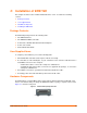
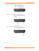
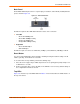
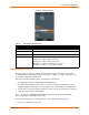
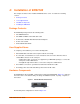
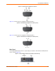
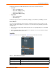
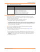
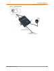
Table Of Contents
- EDS1100/2100 User Guide
- 1: About This Guide
- 2: Overview
- 3: Installation of EDS1100
- 4: Installation of EDS2100
- 5: Using DeviceInstaller
- 6: Configuration Using Web Manager
- 7: Network Settings
- 8: Line and Tunnel Settings
- 9: Terminal and Host Settings
- 10: Services Settings
- 11: Security Settings
- 12: VIP
- 13: Maintenance and Diagnostics Settings
- 14: Advanced Settings
- 15: Branding the EDS1100/2100
- 16: Updating Firmware
- A: Technical Support
- B: Binary to Hexadecimal Conversions
- C: Compliance
- Index
4: Installation of EDS2100
EDS1100/2100 User Guide 26
Figure 4-2 EDS2100 Pinout Configuration for RS-232
Figure 4-3 shows the pinout configuration for RS-422 (4-wire).
Figure 4-3 EDS2100 Pinout Configuration for RS-422 (4-wire)
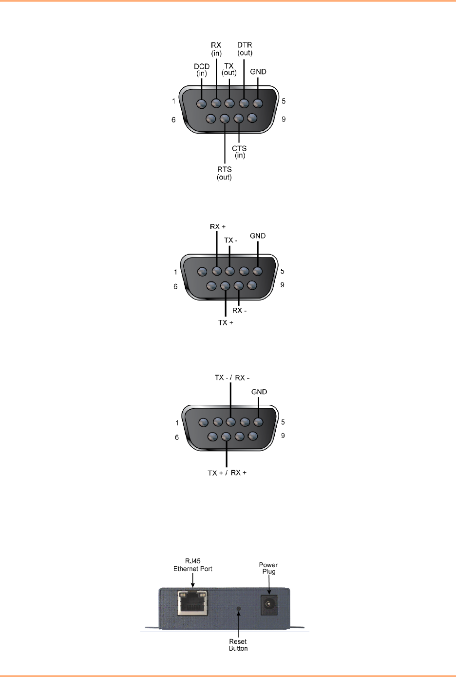
Figure 4-4 shows the pinout configuration for RS-485 (2-wire).
Figure 4-4 EDS2100 Pinout Configuration for RS-485 (2-wire)
Back Panel
On the EDS2100 back panel, there is a power plug, reset button, and an RJ45 (10/100) Ethernet
port as shown in Figure 4-5.
Figure 4-5 EDS2100 Ethernet RJ45 Port, Reset Button, and Power Plug