XPort Pro Lx6 Embedded Device Server User Guide Part Number 900-688-R Revision A December 2013
Intellectual Property © 2013 Lantronix, Inc. All rights reserved. No part of the contents of this book may be transmitted or reproduced in any form or by any means without the written permission of Lantronix. Lantronix and XPort are registered trademarks of Lantronix, Inc. in the United States and other countries. DeviceInstaller is a trademark of Lantronix, Inc. U.S. Patents 6,881,096; 7,018,242. Additional patents pending. Windows and Internet Explorer are registered trademarks of Microsoft Corporation.
Table of Contents Intellectual Property ________________________________________________________ 2 Warranty _________________________________________________________________ 2 Contacts _________________________________________________________________ 2 Disclaimer ________________________________________________________________ 2 Revision History ___________________________________________________________ 2 List of Figures _____________________________________________________________ 7 List of Tables _______
To View Network 1 Interface Status ________________________________________ 25 Network (Ethernet Network “eth0”) Link Settings _________________________________ 25 To Configure Network 1 Link Settings ______________________________________ 26 6: Line and Tunnel Settings 27 Line Settings _____________________________________________________________ 27 To Configure Line Settings _______________________________________________28 To View Line Statistics __________________________________________________ 29 T
HTTP Settings ____________________________________________________________ 45 To Configure HTTP Settings _____________________________________________ 46 To Configure HTTP Authentication _________________________________________ 46 10: Maintenance and Diagnostics Settings 48 Filesystem Settings ________________________________________________________ 48 File Display ___________________________________________________________ 48 To Display Files _______________________________________________________ 48 F
11: Advanced Settings 59 Email Settings ____________________________________________________________ 59 To View, Configure and Send Email ________________________________________ 59 Command Line Interface Settings _____________________________________________ 60 Basic CLI Settings _____________________________________________________ 60 To View and Configure Basic CLI Settings ___________________________________ 60 Telnet Settings ________________________________________________________ 61 To Configure Te
List of Figures Figure 2-1 XPort Pro Lx6 Product Label _______________________________________________15 Figure 4-1 Device Status Page ______________________________________________________ 19 Figure 4-2 Components of the Web Manager Page ______________________________________ 20 Figure 12-1 Uploading New Firmware ________________________________________________ 65 XPort® Pro Lx6 Embedded Device Server User Guide 7
List of Tables Table 4-3 Web Manager Pages _____________________________________________________ 21 Table 5-1 Network Interface Settings _________________________________________________ 23 Table 5-2 Network 1 (eth0) Link Settings ______________________________________________ 25 Table 6-1 Line Configuration Settings ________________________________________________ 27 Table 6-2 Line Command Mode Settings ______________________________________________ 28 Table 6-3 Tunnel Serial Settings _____________________
Table 10-15 Tunnel Default Settings _________________________________________________ 58 Table 10-16 Discovery Settings _____________________________________________________ 58 Table 11-1 Email Configuration _____________________________________________________ 59 Table 11-2 CLI Configuration Settings ________________________________________________ 60 Table 11-3 Telnet Settings ________________________________________________________ 61 Table 11-4 XML Exporting Configuration _______________________________
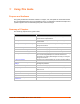
1: Using This Guide Purpose and Audience This guide provides the information needed to configure, use, and update the Lantronix® XPort® Pro Lx6 embedded device server and application server. It is intended for software developers and system integrators who are embedding this product into their designs. Summary of Chapters The remaining chapters in this guide include: Chapter Description 2: Introduction Main features of the product and the protocols it supports. Includes technical specifications.
1: Using This Guide Additional Documentation Visit the Lantronix Web site at www.lantronix.com/support/documentation for the latest documentation and the following additional documentation. Document Description XPort Pro Embedded Device Server Integration Guide Information about the XPort Pro Lx6 hardware, testing the device server using the demonstration board, and integrating the unit into your product.
2: Introduction The XPort Pro Lx6 embedded Ethernet device server is a complete network-enabling solution in a 30 (1.181) X 55 (2.165) X 6.45 (0.248) package. This miniature device server empowers original equipment manufacturers (OEMs) to go to market quickly and easily with Ethernet networking and web page serving capabilities built into their products. Key Features Power Supply: Regulated 3.3V input required. There is a step-down converter to 1.5V for the processor core and 1.
2: Introduction Patient Monitoring Devices Glucose Analyzers Infusion Pumps Protocol Support The XPort Pro Lx6 embedded device server contains a full-featured IP stack. Supported protocols include: ARP, SNMP v1/v2c/v3, IPv4, IPv6, UDP, TCP, ICMP, BOOTP, DHCP, DHCPv6, Auto IP, Telnet, and FTP DNS, TFTP, and Syslog for network communications and management. TCP, UDP, and Telnet tunneling to the serial port. TFTP for uploading/downloading files.
2: Introduction XML: The XPort Pro Lx6 supports XML-based configuration and setup records that make device configuration transparent to users and administrators. XML is easily editable with a standard text or XML editor. (See the XPort Pro Lx6 Embedded Device Server Command Reference Guide for instructions and commands.) Addresses and Port Numbers Hardware Address The hardware address is also referred to as the Ethernet address, physical address, or MAC address.
2: Introduction Figure 2-1 XPort Pro Lx6 Product Label XPort® Pro Lx6 Embedded Device Server User Guide 15
3: Using DeviceInstaller This chapter covers the steps for locating a XPort Pro Lx6 unit and viewing its properties and device details. DeviceInstaller application is a free utility program provided by Lantronix that discovers, configures, upgrades and manages Lantronix device servers. Notes: For instructions on using DeviceInstaller to configure the IP address and related settings or for more advanced features, see the DeviceInstaller Online Help.
3: Using DeviceInstaller Current Settings Description Group Configurable field. Enter a group to categorize the XPort Pro Lx6. Doubleclick the field, type in the value, and press Enter to complete. This group name is local to this PC and is not visible on other PCs or laptops using DeviceInstaller. Comments Configurable field. Enter comments for the XPort. Double-click the field, type in the value, and press Enter to complete.
4: Configuration Using Web Manager This chapter describes how to configure the XPort Pro Lx6 embedded device server using Web Manager, the Lantronix browser-based configuration tool. The unit’s configuration is stored in nonvolatile memory and is retained without power. All changes take effect immediately, unless otherwise noted.
4: Configuration Using Web Manager Device Status Page The Device Status page is the first to appear after you log into Web Manager. The Device Status page also appears when you click Status in the menu bar in Web Manager. Figure 4-1 Device Status Page Note: The Logout button is available on any web page. Logging out of the web page forces re-authentication the next time the web page is accessed.
4: Configuration Using Web Manager Web Manager Components The layout of a typical Web Manager page is below.
4: Configuration Using Web Manager Web Manager pages have these sections: The menu bar always appears at the left side of the page, regardless of the page shown. The menu bar lists the names of the pages available in the Web Manager. To bring up a page, click it in the menu bar. The main area of the page has these additional sections: Links near the top of many pages, such as the one in the example above, enable you to link to additional subpages.
4: Configuration Using Web Manager Web Manager Page (continued) Description See Page Email Shows email statistics and lets you clear the email log, configure email settings, and send an email. 59 Filesystem Shows file system statistics and lets you browse the file system to view a file, 48 create a file or directory, upload files using HTTP, copy a file, move a file, or perform TFTP actions.
5: Network Settings The Network Settings show the status of the Ethernet interface/link and let you configure the settings on the device. Interface settings are related to the configuration of the IP and related protocols. Link settings are related to the physical link connection, which carries the IP traffic. Notes: Some settings require a reboot to take effect. These settings are noted below.
5: Network Settings Network Interface Settings (continued) Description DHCPv6 Client Select to turn On or Off. At bootup, after the physical link is up, the XPort Pro Lx6 will attempt to obtain IPv6 settings from a DHCPv6 server and will periodically renew these settings with the server. On: enables the XPort Pro Lx6 server to obtain IPv6 setting from a DHCPv6 server upon bootup. Off: enables the XPort Pro Lx6 server to obtain IPv4 settings from a DHCP server upon bootup.
5: Network Settings Using the CLI To enter the eth0 command level: enable -> config -> if 1 Using XML Include in your file: To View Network 1 Interface Status Using Web Manager In Network Interface Status, you can view both the current operational settings as well as the settings that would take affect upon a device reboot. To view Ethernet (eth0) Status, click Network on the menu and select Network 1 -> Interface -> Status.
5: Network Settings To Configure Network 1 Link Settings Using Web Manager To modify Ethernet (eth0) Link information, click Network on the menu and select Network 1 > Link > Configuration.
6: Line and Tunnel Settings The XPort Pro Lx6 embedded device server contains one line using a standard RS232/RS485 serial port. This line may be configured to operate in the following modes: RS232 RS485 Full Duplex (also compatible with RS-422) RS485 Half Duplex, with and without termination impedance All serial settings such as Baud Rate, Parity, Data Bits, etc, apply to these lines. Line Settings The Line Settings allow configuration of the serial lines (ports).
6: Line and Tunnel Settings Line Settings Description Xon Char Set Xon Char to be used when Flow Control is set to Software. Prefix decimal with \ or prefix hexadecimal with 0x or prefix a single control character . Xoff Char Set Xoff Char to be used when Flow Control is set to Software. Prefix decimal with \ or prefix hexadecimal with 0x or prefix a single control character .
6: Line and Tunnel Settings To configure a specific line in Command Mode, click Line in the menu and select Line 1 -> Command Mode (Table 6-2). Using the CLI To enter Line 1 command level: enable -> line 1 Using XML Include in your file: Include in your file: To View Line Statistics Using Web Manager To view statistics for Line 1, click Line in the menu and select Line 1 -> Statistics.
6: Line and Tunnel Settings Table 6-3 Tunnel Serial Settings Tunnel Serial Settings Description Line Settings Line Settings information here is display only. Go to the section, To Configure Line Settings to modify these settings. Protocol Protocol information here is display only. Go to the section, To Configure Line Settings to modify these settings. DTR Select the conditions in which the Data Terminal Ready (DTR) control signal on the serial line are asserted.
6: Line and Tunnel Settings Tunnel Packing Mode Settings (continued) Description Timeout Set the timeout value, in milliseconds, after the first character is received on the serial line, before data is sent on the network. Valid range is 1 to 30000 milliseconds. Default is 1000.
6: Line and Tunnel Settings Table 6-5 Tunnel Accept Mode Settings Tunnel Accept Mode Settings Mode Description Set the method used to start a tunnel in Accept mode. Choices are: Local Port Set the port number for use as the network local port. The default local port number for each supported serial line number progresses sequentially in equal value so that Tunnel X : 1000X. For example: Protocol Disable = do not accept an incoming connection.
6: Line and Tunnel Settings Tunnel Accept Mode Settings (continued) Password Description Enter a password. This password can be up to 31 characters in length and must contain only alphanumeric characters and punctuation. When set, clients must send the correct password string to the unit within 30 seconds from opening network connection in order to enable data transmission.
6: Line and Tunnel Settings For Connect Mode using UDP, the XPort Pro Lx6 accepts packets from any device on the network. It will send packets to the last device that sent it packets. Note: The Port in Connect Mode is not the same port configured in Accept Mode. The TCP keepalive time is the time in which probes are periodically sent to the other end of the connection. This ensures the other side is still connected.
6: Line and Tunnel Settings Tunnel Connect Mode Settings (continued) Description Email on Disconnect Select an email profile number to which an email notification will be sent upon the disconnection of an accept mode tunnel. CP Output Enter the CP Output Group whose value should change when a connection is established and dropped. Connection Value specifies the value to set the CP Group to when a connection is established.
6: Line and Tunnel Settings To Configure Tunnel Disconnect Mode Settings Using Web Manager To configure the Disconnect Mode for a specific tunnel, click Tunnel in the menu and select Tunnel 1 -> Disconnect Mode.
6: Line and Tunnel Settings Tunnel Modem Emulation Settings Description Connect String Enter the customized Connect String sent to the Serial Line with the Connect Modem Response Code. Display Remote IP Set whether the Display Remote IP is enabled so that the incoming RING sent on the Serial Line is followed by the IP address of the caller.
7: Terminal and Host Settings Predefined connections are available via Telnet or a serial port. A user can choose one of the presented options and the device automatically makes the predefined connection. Either the Telnet or serial port connection can present the CLI or the Login Connect Menu. By default, the CLI is presented when the device is accessed. When configured to present the Login Connect Menu, the hosts configured via the Host selections, and named serial lines are presented.
7: Terminal and Host Settings To Configure the Terminal Network Connection Using Web Manager To configure the Terminal on Network, click Terminal on the menu and select Network -> Configuration. To configure the Terminal on Network, click Line 1 on the menu and select Network -> Configuration. To configure the Terminal on Network, click Line 2 on the menu and select Network -> Configuration.
8: Configurable Pin Manager The Configurable Pin Manager is responsible for assignment and control of the configurable pins (CPs) available on the XPort Pro Lx6 embedded device service. There are three configurable pins on the XPort Pro Lx6. You must configure the CPs by making them part of a group. A CP Group may consist of one or more CPs. This increases flexibility when incorporating the XPort Pro Lx6 into another system.
8: Configurable Pin Manager CPM – CPs Status Description Binary Shows the binary assertion value of the corresponding bit. CP# Shows the CP number. Groups Lists the groups in which the CP is a member. Notes: To modify a CP, all groups in which it is a member must be disabled. The changes to a CP configuration are not saved in FLASH. Instead, these CP settings are used when the CP is added to a CP Group. When the CP Group is saved, its CP settings are saved with it.
8: Configurable Pin Manager To Configure CPM Settings Using Web Manager To configure a configurable pin, click CPM in the menu, select CPs and then the desired CP to configure. To configure a CPM Group, click CPM in the menu, select Groups and then the desired Group Name to configure.
9: Services Settings DNS Settings This section describes the active run-time settings for the domain name system (DNS) protocol. The primary and secondary DNS addresses come from the active interface. The static addresses from the Network Interface configuration settings may be overridden by DHCP. Note: The blue text in the XML command strings of this chapter are to be replaced with a user-specified name.
9: Services Settings FTP Settings The FTP protocol can be used to upload and download user files, and upgrade the XPort Pro Lx6 firmware. A configurable option is provided to enable or disable access via this protocol. Table 9-2 FTP Settings FTP Settings Description State Select to enable or disable the FTP server: Enabled (default) Disabled To Configure FTP Settings Using Web Manager To configure FTP, click FTP in the menu.
9: Services Settings Syslog Settings (continued) Severity Log Level Description Specify the minimum level of system message the XPort Pro Lx6 should log. This setting applies to all syslog facilities. The drop-down list in the Web Manager is in descending order of severity (e.g., Emergency is more severe than Alert.) To View or Configure Syslog Settings Using Web Manager To configure the Syslog, click Syslog in the menu.
9: Services Settings HTTP Settings (continued) Description Log Format Set the log format string for the HTTP server.
9: Services Settings Using the CLI To enter the HTTP command level: enable -> config -> http Using XML Include in your file: XPort® Pro Lx6 Embedded Device Server User Guide 47
10: Maintenance and Diagnostics Settings Filesystem Settings Use the file system to list, view, create, upload, copy, move, remove, and transfer files. The XPort Pro Lx6 embedded device server uses a flash file system to store files. File Display It is possible to view the list of existing files, and to view their contents in the ASCII or hexadecimal formats. Table 10-1 File Display Settings File Display Commands Description ls Displays a list of files on the XPort Pro Lx6, and their respective sizes.
10: Maintenance and Diagnostics Settings File Modification The XPort Pro Lx6 allows for the creation and removal of files on its filesystem. Table 10-2 File Modification Settings File Modification Commands Description rm Removes the specified file from the file system. touch Creates the specified file as an empty file. cp Creates a copy of a file. mkdir Creates a directory on the file system. rmdir Removes a directory from the file system. format Format the file system and remove all data.
10: Maintenance and Diagnostics Settings To Transfer or Modify Filesystem Files Using Web Manager To create a new file or directory, upload an existing file, copy or move a file, click Filesystem in the menu and select Browse. Using the CLI To enter the Filesystem command level: enable -> filesystem Using XML Not applicable. Protocol Stack Settings There are various low level network stack specific items that are available for configuration.
10: Maintenance and Diagnostics Settings ICMP and ICMPv6 Settings Table 10-5 ICMP Network Stack Settings Protocol Stack ICMP Settings Description State The State selection is used to turn on/off processing of ICMP messages. This includes both incoming and outgoing messages. Choose Enabled or Disabled. To Configure ICMP Network Stack Settings Using Web Manager To configure ICMP protocol settings, click Protocol Stack in the menu and select ICMP.
10: Maintenance and Diagnostics Settings To Configure ARP Network Stack Settings Using Web Manager To configure ARP protocol settings, click Protocol Stack in the menu and select ARP.
10: Maintenance and Diagnostics Settings Diagnostics The XPort Pro Lx6 has several tools for diagnostics and statistics. Various options allow for the configuration or viewing of IP socket information, ping, traceroute, memory, and processes. Hardware To View Hardware Information Using Web Manager To view hardware information, click Diagnostics in the menu and select Hardware.
10: Maintenance and Diagnostics Settings Ping The ping command can be used to test connectivity to a remote host. Table 10-8 Ping Settings Diagnostics: Ping Description Settings (continued) Host Enter the IP address or host name for the XPort Pro Lx6 to ping. Count Enter the number of ping packets XPort Pro Lx6 should attempt to send to the Host. The default is 3. Timeout Enter the time, in seconds, for the XPort Pro Lx6 to wait for a response from the host before timing out.
10: Maintenance and Diagnostics Settings Using the CLI To enter the command level: enable Using XML Not applicable. Log Table 10-10 Log Settings Diagnostics: Log Output Description Select a diagnostic log output type: Max Length Disable - Turn off the login feature. Filesystem - Directs logging to /log.txt. Line 1- Directs logging to the selected serial line. Set the maximum length of the log.txt file. Max length must range from 10 - 128 kbytes.
10: Maintenance and Diagnostics Settings Using the CLI To enter the command level: enable -> device, show memory Using XML Include in your file: Processes The XPort Pro Lx6 Processes information shows all the processes currently running on the system. It shows the Process ID (PID), Parent Process ID (PPID), user, CPU percentage, percentage of total CPU cycles, and process command line information.
10: Maintenance and Diagnostics Settings System Settings The XPort Pro Lx6 System settings allow for rebooting the device, restoring factory defaults, uploading new firmware and updating a system’s short and long name. Note: Anytime you reboot the unit, this operation will take some time to complete. Please wait a minimum of 25-30 seconds after rebooting the unit before attempting to make any subsequent connections.
10: Maintenance and Diagnostics Settings Table 10-13 Line Configuration Default Settings Protocol Tunnel Baud Rate 9600 Flowcontrol None Table 10-14 Network Configuration Default Settings BOOTP Disabled DHCP Enabled DHCPv6 Enabled IPv6 AutoConf Diabled Syslog state Disabled Table 10-15 Tunnel Default Settings Accept Mode Enabled Connect Mode Disabled Discovery The current statistics and configuration options for device discovery are available for the XPort Pro Lx6.
11: Advanced Settings Email Settings View and configure email alerts relating to events occurring within the system. Table 11-1 Email Configuration Email – Configuration Description Settings To Enter the email address to which the email alerts will be sent. Multiple addresses are separated by semicolon (;). Required field if an email is to be sent. CC Enter the email address to which the email alerts will be copied. Multiple addresses are separated by semicolon (;).
11: Advanced Settings Using XML Include in your file: Command Line Interface Settings The Command Line Interface settings allow you to control how users connect to and interact with the command line of the XPort Pro Lx6 embedded device server. It is possible to configure access via the Telnet protocols, in addition to general CLI options. Basic CLI Settings The basic CLI settings control general CLI access and usability options.
11: Advanced Settings Telnet Settings The Telnet settings control CLI access to the XPort Pro Lx6 over the Telnet protocol. Table 11-3 Telnet Settings Telnet Settings Description Telnet State Enable or Disable CLI access via Telnet Telnet Port Enter an alternative Telnet Port to override the default used by the CLI server. Blank the field to restore the default. Telnet Max Sessions Specify the maximum number of concurrent Telnet sessions that will be allowed.
11: Advanced Settings Table 11-4 XML Exporting Configuration XML Export Configuration Settings Description Export to browser Select this option to export the XCR data in the selected fields to the browser. Use the “xcr dump” command to export the data to the browser. Export to local file Select this option to export the XCR data to a file on the device. If you select this option, enter a file name for the XML configuration record. Use the “xcr export” command to export the data to a local file.
11: Advanced Settings XML Export Status Settings (continued) Description Groups to Export Check the configuration groups that are to be exported to the XML configuration record. The group list should be comma delimited and encased in double quotes. The list of available groups can be viewed with the “xcr list” command. To Export in XML Format Using Web Manager To export configuration format, click XML in the menu and select Export Status.
11: Advanced Settings Whole Groups to Import Select the configuration groups to import from the XML configuration record. This option imports all instances of each selected group. Text List Enter the string to import specific instances of a group. The textual format of this string is: :;:;... Each group name is followed by a colon and the instance value and each : value is separated by a semi-colon. If a group has no instance then only the group name should be specified.
12: Updating Firmware Obtaining Firmware Obtain the most up-to-date firmware and release notes for the unit from the Lantronix Web site (www.lantronix.com/support/downloads/) or by using anonymous FTP (ftp://ftp.lantronix.com/). Loading New Firmware through Web Manager Upload the firmware using the device web manager System page. To upload new firmware: 1. Select System in the menu bar. The System page appears. Figure 12-1 Uploading New Firmware 2.
12: Updating Firmware 3. Select the file and click Open. The selected file name appears on. 4. Click Upload to install the firmware on the XPort Pro Lx6 embedded device server. 5. Click OK in the confirmation popup which appears. The firmware will be installed and the device will automatically reboot afterwards. 6. Close and reopen the web manager internet browser to view the device’s updated web pages.
13: Branding the XPort Pro Lx6 This chapter describes how to brand your XPort Pro Lx6 embedded device server by using Web Manager and Command Line Interface (CLI). It contains the following sections on customization: Web Manager Customization Short and Long Name Customization Web Manager Customization Customize the Web Manager's appearance by modifying index.html, style.css, and the product logo. The style (fonts, colors, and spacing) of the Web Manager is controlled with style.css.
13: Branding the XPort Pro Lx6 Short and Long Name Customization You can customize the short and long names in your XPort Pro Lx6 device. The names display in the CLI show command and in the System web page in the Current Configuration table. The short name is used for the show command. Both names display in the CLI Product Type field. Table 13-1 Short and Long Name Settings Name Settings Description Short Name Enter a short name for the system name. A maximum of 32 characters are allowed.
Appendix A: Technical Support If you are unable to resolve an issue using the information in this documentation, please the contact Technical Support. North America Hours: 6:00am - 5:00pm Pacific Time Mon. - Fri. (excluding holidays) www.lantronix.com/support/ FTP: ftp.lantronix.com Tel: (800) 422-7044 (US Only) Tel: (949) 453-7198 Fax: (949) 450-7226 Europe, Middle East, Africa (EMEA) www.lantronix.com/support/ Tel: +31 (0)76 52 36 740 Japan japan_sales@lantronix.
Appendix A:Technical Support Online Support options listed below are available 24 hours a day, 7 days a week at the Lantronix support page at http://www.lantronix.
Appendix B: Compliance (According to ISO/IEC Guide 17050-1, 17050-2 and EN 45014) Manufacturer's Name & Address: Lantronix, Inc.
Appendix B: Compliance RoHS Notice All Lantronix products in the following families are China RoHS-compliant and free of the following hazardous substances and elements: Lead (Pb) Cadmium (Cd) Product Family Name Mercury (Hg) Hexavalent Chromium (Cr (VI)) Polybrominated biphenyls (PBB) Polybrominated diphenyl ethers (PBDE) Toxic or hazardous Substances and Elements Lead (Pb) Mercury (Hg) Cadmium (Cd) Hexavalent Chromium (Cr (VI)) Polybrominate d biphenyls (PBB) Polybrominated diphenyl e
Appendix C: Binary to Hexadecimal Conversions Many of the unit's configuration procedures require you to assemble a series of options (represented as bits) into a complete command (represented as a byte). The resulting binary value must be converted to a hexadecimal representation. Use this chapter to learn to convert binary values to hexadecimals or to look up hexadecimal values in the tables of configuration options.
Appendix C: Binary to Hexadecimal Conversions Figure C-2 Windows Scientific Calculator 4. Click Hex. The hexadecimal value appears.