
Integration Guide

2:Description and Specifications
MatchPort b/g Pro Integration Guide 13
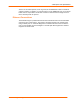
Warning: The MatchPort b/g Pro has two 4.7K pull-ups on the E_LINKLED
and E_ACTLED signals to set up the PHY’s LED Indicator Mode as Ethernet
Link and Activities at Power On Reset (POR). Do not connect these two
signals with any pull-down resistors as they may corrupt the logic level on
these two signals at POR, causing undesired operation.
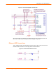
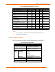
Wireless LED Connections
The W_LINKLED is driven by the Radio Module. It is active low. Recommended
connections on the target board are shown below.
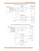
Figure TBD. Recommended LED Connections
Output W_LINKLED can be used to drive an external LED to monitor the activity
of the radio. The output is active when the receiver and or transmitter are on. The
output is active low and can drive an LED with 10mA max.
If WLAN Power Management is disabled, and when the unit is associated with a network,
the receiver will always be on and thus any LED output, that indicates the receiver or
transmitter being on will be active continuously.
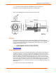
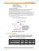
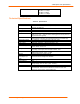
Antenna Mating Connector
An antenna connection is made via the U.FL style connector on the MatchPort. Lantronix
offers two cable options, reverse-SMA to U.FL (P/N 500-180-R) or U.FL to U.FL (P/N
500-181-R).
Figure 2-4. Reverse-SMA to U.FL (P/N 500-180-R)
Figure 2-5. U.FL to U.FL Cable (P/N 500-181-R)