
Integration Guide


2:Description and Specifications
MatchPort b/g Pro Integration Guide 15
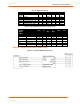
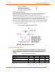
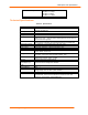
Table 2-1. RS232 Connections
MatchPort b/g Pro
DCE Connector
DTE Connector
Signal
(Logic)
Description
DB9
DB25
Signal
DB9
DB
25
Signal
RXD1 Data In 2 3 RXD1 3 2 TXD1
TXD1 Data Out 3 2 TXD1 2 3 RXD1
RTS1 H/W Flow Control Output
7 4 RTS1 8 5 CTS1
CTS1 H/W Flow Control Input 8 5 CTS1 7 4 RTS1
CPx Modem Control Input 1 8 DCD 4 20 DTR
CPy Modem Control Output 4 20 DTR 1 8 DCD
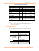
Table 2-2. JP6 RS422/485 Connections on Demo board
MatchPort
b/g Pro
Signal
(logic)
Description
RS485
Signal
JP6
Pin
DB25
4
Wire
DB25
2
Wire
DB9
4 wire
DB9
2 wire
TXD1 Data Out
TX+485 4 14 14 7 7
TXD1 Data Out
TX-485 3 15 15 3 3
RXD1 Data In
RX+485 2 21 14 2 7
RXD1 Data In
RX-485 1 22 15 8 3
RTS1 TX Enable
CP3 RS485 Select
CP4 RS485 2-wire
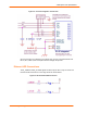
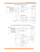
Sample Layouts for RS485 Connectivity
Figure 2-7. Combined RS232/422 Transceiver