
Integration Guide
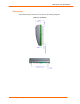
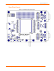

3:Demonstration Kit
MatchPort b/g Pro Integration Guide 27
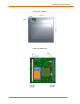
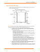
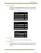
Configuration Switch Bank
Table 3-3. Demo Board JP1 Jumper Configuration
JP1 pin/Signal
JP1 pin/Signal
Function
1/CP1 2/LED12 Jumper 1-2, CP1 Controls LED12
3/CP2 4/LED11 Jumper 3-4, CP2 Controls LED11
5/CP3 6/LED10 Jumper 5-6, CP3 Controls LED10
7/CP4 8/LED9 Jumper 7-8, CP4 Controls LED9
9/CP5 10/LED8 Jumper 9-10, CP5 Controls LED8
11/CP6 12/LED7 Jumper 11-12, CP6 Controls LED7
13/CP7 14/LED6 Jumper 13-14, CP7 Controls LED6
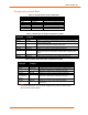
Table 3-4. Demo Board JP7 Jumper Configuration for CON1
JP7
pin/Signal
JP7
pin/Signal
Function
1/TXD1 2/TXA Jumper 1-2, Send TXD to RS232/485 transceiver.
3/RTS1 4/RTSA Jumper 3-4, Send RTS to RS232/485 transceiver. In 485 mode RTS
controls transmit enable.
5/CP3 6/SEL4XXA Jumper 5-6, CP3 high selects 485 mode, low 232 mode. Pin at
transceiver is pulled down to default to 232 mode.
7/RXD1 8/RXA Jumper 7-8, Receive RXD from RS232/485 transceiver.
9/CTS1 10/CTSA Jumper 9-10, Receive CTS from RS232 transceiver.
11/CP4 12/HDPX4XXA Jumper 11-12. In 485 mode, CP4 selects full duplex when low and half
duplex when high. Pin at transceiver is pulled down to default to full
duplex.
13/CP1 14/DTRA Jumper 13-14, CP1 drives DTR to RS232 transceiver.
15/CP2 16/DCDA Jumper 15-16, CP2 receives DCD from RS232 transceiver.
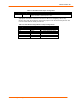
Table 3-xx. Demo Board JP8 Jumper Configuration for CON2
JP7
pin/Signal
JP7
pin/Signal
Function
1/TXD2 2/TXB Jumper 1-2, Send TXD to RS232 transceiver.
3/RTS2 4/RTSB Jumper 3-4, Send RTS to RS232 transceiver.
5/CP7 6/SEL4XXB Do
not
add jumper since only RS232 is supported. Pin at
transceiver is pulled down to default to 232 mode.
7/RXD2 8/RXB Jumper 7-8, Receive RXD from RS232 transceiver.
9/CTS2 10/CTSB Jumper 9-10, Receive CTS from RS232 transceiver.
11/RESERVED
on MatchPort
b/g Pro
12/HDPX4XXB Do
not
add jumper since only RS232 is supported. Pin at
transceiver is pulled down to default to 232 mode.
13/CP5 14/DTRB Jumper 13-14, CP5 drives DTR to RS232 transceiver.
15/CP6 16/DCDB Jumper 15-16, CP6 receives DCD from RS232
transceiver.
Note: CP arrangement in the tables above is for demonstration purpose only. In
customers’ applications, any CP can be assigned as a function of DTR or DCD.
All CPs can be used as GPIOs.