
Integration Guide
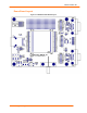

3:Demonstration Kit
MatchPort b/g Pro Integration Guide 28
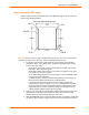
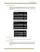
Table 3-5. Demo Board JP5 Jumper Configuration
Pin/Signal
Pin/Signal
Function
1/3V3 2/3V3_UUT MatchPort UUT power input jumper for current measurement. Jumper 1-2
must be installed to provide power to UUT.
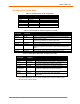
If using CPs for any combination of the demo board configurations above, please use the
appropriate CP function selection as shown in Table 3-5. If assigning a CP for any
function other than the serial port, remove the jumper for the associated CP pin from JP7
to avoid conflict with the serial port function.
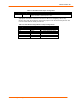
Table 3-5. Demo Board Configurable Pin Jumper Configurations.
Configurable Pin
JP1 Function
JP7,JP8 Function
CP1 LED12 JP7, CON1 DTR
CP2 LED11 JP7, CON1 DCD
CP3 LED10 JP7, CON1 RS485/232 Select
CP4 LED9 JP7, CON1 RS485 Duplex Select
CP5 LED8 JP8, CON2 DTR
CP6 LED7 JP8, CON2 DCD
CP7 LED6 JP8, leave open