
Integration Guide


MatchPort b/g Pro Integration Guide 6
Figure 2-1. MatchPort b/g Pro Top and Front Views .................. Error! Bookmark not defined.
Figure 2-2. MatchPort b/g Pro Block Diagram .......................................................................... 9
Figure 2-3. Connection Diagram to an RJ45 Jack .................................................................. 12
Figure 2-4. Recommended LED Connections ........................................................................ 12
Figure 2-5. Combined RS232/422 Transceiver....................................................................... 15
Figure 2-6. Separate RS232/422 Transceivers....................................................................... 16
Figure 2-7. Separate RS422 Transceivers for 2-Wire and 4-Wire Setups ............................... 16
Figure 2-8. BOOTP_EN# APPLICATION CIRCUIT ................................................................ 18
Figure 2-9. Side Views ........................................................................................................... 21
Figure 2-10. Top View ........................................................................................................... 22
Figure 2-11. Bottom View ...................................................................................................... 22
Figure 2-12. PCB Layout (Top View) ...................................................................................... 23
Figure 2-13. Product Label .................................................................................................... 24
Figure 3-1. MatchPort Demo Board Layout ............................................................................ 29
Figure 3-2. Demo Board Block Diagram ................................................................................. 30
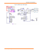
Figure 3-3. Schematic............................................................................................................ 31
List of Tables
Table 2-1. RS232 Connections .............................................................................................. 15
Table 2-2. JP6 RS422/485 Connections on Demo board ....................................................... 15
Table 2-3. Absolute Maximum Ratings ................................................................................... 18
Table 2-4. Recommended Operating Conditions .................................................................... 19
Table 2-5. Specifications....................................................................................................... 20
Table 3-1. RS-232 Signals on Serial Port 1 ............................................................................ 26
Table 3-2. RS-422 4-Wire Connector on Serial Port 1 ............................................................ 26
Table 3-3. Demo Board JP1 Jumper Configuration ................................................................ 27
Table 3-4. Demo Board JP7 Jumper Configuration for CON1 ................................................. 27
Table 3-5. Demo Board JP5 Jumper Configuration ................................................................ 28