UDS10 UDS100 User Guide Part Number 900-360 Revision A June 2004
Copyright & Trademark © 2004, Lantronix. All rights reserved. No part of the contents of this book may be transmitted or reproduced in any form or by any means without the written permission of Lantronix. Printed in the United States of America. Ethernet is a trademark of XEROX Corporation. UNIX is a registered trademark of The Open Group. Windows 95, Windows 98, Windows 2000, and Windows NT are trademarks of Microsoft Corp. Netscape is a trademark of Netscape Communications Corporation.
Disclaimer & Revisions Operation of this equipment in a residential area is likely to cause interference, in which case the user, at his or her own expense, will be required to take whatever measures may be required to correct the interference. Note: This product has been designed to comply with the limits for a Class A digital device pursuant to Part 15 of FCC Rules. These limits are designed to provide reasonable protection against such interference when operating in a commercial environment.
Contents Contacts 2 1: Using This Guide 8 Purpose and Audience________________________________________________ 8 Chapter Summary ___________________________________________________ 8 Additional Documentation _____________________________________________ 9 2: Introduction 10 Applications _______________________________________________________ Application Examples________________________________________________ Protocol Support ___________________________________________________ Additional Features ___
UDS10/UDS100 User Guide Remote IP Address ______________________________________________ Remote Port ___________________________________________________ Disconnect Mode _______________________________________________ Flush Mode ____________________________________________________ Pack Control ___________________________________________________ Disconnect Time (Inactivity Timeout) ________________________________ Send Characters ________________________________________________ Telnet Terminal Type __________
UDS10/UDS100 User Guide Network Port ___________________________________________________ 53 Ethernet Connector Pinouts _______________________________________ 54 10: Technical Specifications 55 UDS10 Technical Specifications _______________________________________ 55 UDS100 Technical Specifications ______________________________________ 56 A: Alternative Ways to Assign an IP Address DHCP ________________________________________________________ AutoIP ____________________________________________________
UDS10/UDS100 User Guide Figure 9-4. Null-Modem Cable (Lantronix Part No. 500-163) ___________________ 53 Figure 9-5. Network Interface ___________________________________________ 53 Figure 9-6. RJ45 Ethernet Connector _____________________________________ 54 Tables Table 5-1. Standard IP Network Netmasks _________________________________ Table 5-2. Netmask Examples __________________________________________ Table 5-3. Interface Mode Options _______________________________________ Table 5-4.
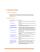
1: Using This Guide Purpose and Audience This guide provides the information needed to configure, use, and update the UDS device server. It is for system administrators and those responsible for installing and maintaining the UDS. Chapter Summary The remaining chapters in this guide include: 2: Introduction Describes the main features of the UDS and the protocols it supports. 3: Getting Started Provides information for installing your unit and getting it up and running.
UDS10/UDS100 User Guide Using This Guide Additional Documentation The following information is available on the product CD or the Lantronix Web site:www.lantronix.com DeviceInstaller User Guide “Live” Tutorials on the Lantronix Web Site Provides instructions for using the Windows-based utility to configure the UDS and other Lantronix device servers. (CD and web site) Explain and demonstrate Assigning an IP address to the UDS and Setting up the UDS and the Redirector. See http://ts.lantronix.
2: Introduction The UDS10 and UDS100 are single-port device servers that provide a quick, simple, and cost-effective way to bring the advantages of data accessibility and remote management to devices not currently connected to a network. The main difference between the two models is that the UDS100 provides both half and full duplex 10/100 Ethernet data transfer, whereas the UDS10 provides only half duplex 10Base-T Ethernet. The technical specifications of the two products differ slightly as well.
UDS10/UDS100 User Guide Introduction Figure 2-1. Application Examples Note: For step-by-step instructions on configuring the UDS for serial tunneling or for use with the Com Port Redirector, access the UDS Configuration Tutorials using Web Manager. (See Accessing Web Manager on page 18.
Introduction UDS10/UDS100 User Guide Protocol Support The UDS uses the Internet Protocol (IP) for network communications and the Transmission Control Protocol (TCP) to assure that no data is lost or duplicated and everything sent to the connection arrives correctly at the target. Supported protocols include: ARP, UDP, TCP, ICMP, Telnet, TFTP, AutoIP, DHCP, HTTP, and SNMP for network communications. TCP, UDP, and Telnet for connections to the serial port. TFTP for firmware updates.
UDS10/UDS100 User Guide Introduction Product Information Label The product information label on the underside of the unit contains the following information about your specific unit: Bar code Serial number Product ID (name) Product description Hardware address (also referred to as the Ethernet or MAC address) The first three bytes of the hardware address are fixed and read 00-20-4A, identifying the unit as a Lantronix product.
3: Getting Started This chapter describes how to get your UDS up and running in the shortest possible time. Installing the UDS Figure 3-1. UDS Connected to Serial Device and Network To install the unit, complete the following steps in order. Refer to the numbers in the figure above. 1. Connect a serial device to your unit. See 9: Connections and Pinouts for more information about the device attachments the unit supports. 2. Connect an Ethernet cable to the RJ45 port. 3.
UDS10/UDS100 User Guide Getting Started Required Information Before configuring the UDS, have the following information available: Hardware Address Take note of the unit’s hardware address (also known as the Ethernet or MAC address). It is on the product label, in the format: 00-20-4a-XX-XX-XX, where the XXs are unique numbers assigned to the product (see Product Information Label on page13). Hardware Address: 00-20-4a-_____-_____-_____ IP Address The UDS must have a unique IP address on your network.
Getting Started UDS10/UDS100 User Guide Assigning the IP Address and Related Network Settings This section describes two ways to assign the IP address and related network settings quickly. DeviceInstaller Serial Port Login DeviceInstaller Note: The DeviceInstaller User Guide and the DeviceInstaller online help provide more detailed information on using DeviceInstaller. Installing DeviceInstaller To use the DeviceInstaller utility, you first install it from the product CD. 1.
UDS10/UDS100 User Guide Getting Started Adding the Unit to the Manage List Now add the unit to the list of similar Lantronix devices on the network so that you can manage and configure it. To perform this step, click the Search icon. DeviceInstaller locates the unit and adds it to the list. Now you can manage (configure) the unit so that it works with the serial device on the network.
4: Configuring the UDS Using Web Manager You must configure the UDS so that it can communicate on a network with your serial device. For example, you must set the way the unit responds to serial and network traffic, handles serial packets, and starts and closes connections. This chapter gives an overview of the procedure for using Web Manager to configure a UDS. This is the easiest and preferred method. The unit’s configuration is stored in nonvolatile memory (NVRam) and is retained without power.
UDS10/UDS100 User Guide Configuring the UDS Using Web Manager Figure 4-2. UDS Configuration Guidelines Page UDS settings opens a configuration window to configure the UDS10/UDS100, as shown in Figure 4-3. Serial cabling lets you view pinouts for the UDS serial port. View UDS Configuration Tutorials provides step-by-step instructions for configuring serial tunneling and the Com Port Redirector. Technical Support lets you download the latest firmware for your UDS and view documentation.
Configuring the UDS Using Web Manager UDS10/UDS100 User Guide Using Web Manager 1. To configure the unit, select UDS Settings on the UDS Configuration Guidelines Page. The Web Manager page displays. Figure 4-3. Lantronix Web Manager 2. Use the menu (pushbuttons) to navigate to sub pages where you can configure server settings. Note: For detailed explanations of the settings, see 5: Configuring the UDS Using Telnet or the Serial Port. 3.
UDS10/UDS100 User Guide Configuring the UDS Using Web Manager Figure 4-4. Server Properties Configuration on the Web Browser 3. In the Telnet Password field, enter a password to prevent unauthorized access to the Setup Mode using a Telnet connection to port 9999. The password is limited to 4 characters. (An enhanced password setting of 16 characters is available under Security Settings in Setup Mode.) Note: No password is required to access the Setup Mode window using a serial connection. 4.
5: Configuring the UDS Using Telnet or the Serial Port You must configure the UDS so that it can communicate on a network with your serial device. For example, you must set the way the unit will respond to serial and network traffic, how it will handle serial packets, and when to start or close a connection. As an alternative to using Web Manager, configure the UDS using a series of prompts referred to as Setup Mode, accessed using a Telnet or a serial port connection.
UDS10/UDS100 User Guide Configuring the UDS Using Telnet or the Serial Port Figure 5-2. Setup Mode 3. Select an option on the Change Setup menu by entering the number of the option in the Your choice ? prompt and pressing Enter. 4. To enter a value for a parameter, type the value and press Enter. To confirm a current value, just press Enter. 5. When you are finished, save the new configurations (option 9). The unit reboots.
Configuring the UDS Using Telnet or the Serial Port UDS10/UDS100 User Guide 2. Type three lowercase x characters (xxx) within one second after powering up to start the configuration mode. Note: The easiest way to enter Setup Mode is to hold down the x key on your keyboard while powering up the unit. The configuration settings display, followed by the Change Setup menu. 3. Select an option on the menu by entering the number of the option in the Your choice ? prompt and pressing Enter. 4.
UDS10/UDS100 User Guide Configuring the UDS Using Telnet or the Serial Port Note: Class A: 24 bits; Class B: 16 bits; Class C: 8 bits. The unit prompts for the number of host bits to enter, then calculates the netmask, which displays in standard decimal-dot notation when the saved parameters display (for example, 255.255.255.0). Table 5-1. Standard IP Network Netmasks Network Class Host Bits Netmask A B C 24 16 8 255.0.0.0 255.255.0.0 255.255.255.0 Table 5-2. Netmask Examples Netmask Host Bits 255.
Configuring the UDS Using Telnet or the Serial Port UDS10/UDS100 User Guide If you give the unit an IP of 0.0.0.0, you then have the option to assign an 8-character DHCP name. Figure 5-4. Server Configuration Option Change DHCP device name (LTRX) ? (N) Y Enter new DHCP device name : LTRXYES Channel 1 Configuration (Serial Port Settings) Note: Some fields require entries in hexadecimal notation.
UDS10/UDS100 User Guide Configuring the UDS Using Telnet or the Serial Port The following table displays available I/F Mode options: Table 5-3. Interface Mode Options I/F Mode Option Bit 7 6 5 4 3 2 1 0 RS-232C RS-422/485 RS-485 2-wire 7 Bit 8 Bit No Parity Even Parity Odd Parity 1 Stop bit 2 Stop bit 0 0 0 1 1 1 1 0 1 1 0 0 1 1 0 1 0 1 1 1 The following table demonstrates how to build some common Interface Mode settings: Table 5-4.
Configuring the UDS Using Telnet or the Serial Port UDS10/UDS100 User Guide Table 4-5. Reserved Port Numbers Port Numbers Reserved for 1 – 1024 Reserved (well known ports) 9999 Telnet setup 30718 Reserved (77FEh) Warning: We recommend that you not use the reserved port numbers for this setting as incorrect operation may result. Use port 0 for the outgoing local port to change with each connection. The port range is 50,000 to 59,999. Each subsequent connection increments the number by 1.
UDS10/UDS100 User Guide Configuring the UDS Using Telnet or the Serial Port Manual Connection The UDS attempts to connect when directed by a command string received from the serial port. The first character of the command string must be a C (ASCII 0x43), and the last character must be either a carriage return (ASCII 0x0D) or a line feed (0x0A). No spaces may be in the command string.
Configuring the UDS Using Telnet or the Serial Port UDS10/UDS100 User Guide Figure 5-6. Hostlist Option To use the hostlist option, follow these steps: 1. To enable the hostlist, enter a Connect Mode of 0x20 (2X). The menu shows you a list of current entries already defined in the product. 2. To delete, modify, or add an entry, select Yes. If you enter an IP address of 0.0.0.0, that entry and all others after it are deleted. 3.
UDS10/UDS100 User Guide Configuring the UDS Using Telnet or the Serial Port accumulating phone charges for each connection. Modem Mode allows you to replace modems with UDS units, and to use an Ethernet connection instead of a phone call. By not having to change communications applications, you avoid potentially expensive phone calls. To select Modem Mode, set the Connect Mode to C6 (no echo), D6 (echo with full verbose), or D7 (echo with 1-character response).
Configuring the UDS Using Telnet or the Serial Port UDS10/UDS100 User Guide Table 5-8. Modem Mode Commands Modem Mode Command Function ATDTx.x.x.x,pppp Makes a connection to an IP address (x.x.x.x) and a remote port number or (pppp). ATDTx.x.x.x/pppp Makes a connection to an IP address (x.x.x.x) and the remote port number ATDTx.x.x.x defined within the unit. Forces the unit into Monitor Mode if a remote IP address and port number ATD0.0.0.0 are defined within the unit.
UDS10/UDS100 User Guide Configuring the UDS Using Telnet or the Serial Port Disconnect Mode This option determines the conditions under which the unit causes a network connection to terminate. In DisConnMode, DTR drop either drops the connection or is ignored. Note: To look up hex values, see B: Binary to Hexadecimal. Table 5-9.
Configuring the UDS Using Telnet or the Serial Port UDS10/UDS100 User Guide Pack Control Two firmware-selectable packing algorithms define how and when the unit sends packets to the network. The standard algorithm is optimized for applications in which the unit is used in a local environment, allowing for very small delays for single characters while keeping the packet count low.
UDS10/UDS100 User Guide Configuring the UDS Using Telnet or the Serial Port Disconnect Time (Inactivity Timeout) Use Disconnect Time to set an inactivity timeout. The unit drops the connection if there is no activity on the serial line before the set time expires. Enter time in the following format: mm:ss, where m is the number of minutes and s is the number of seconds. To disable the inactivity timeout, enter 00:00. Range is 0 (disabled) to 5999 seconds (99 minutes, 59 seconds). The default is 0.
Configuring the UDS Using Telnet or the Serial Port UDS10/UDS100 User Guide TCP Keepalive time in s This option defines how many seconds the unit waits during a silent connection before checking to see whether the currently connected network device is still on the network. If the unit does not receive a response, it drops that connection. ARP Cache timeout in s When the unit communicates with another device on the network, it adds an entry into its ARP table.
UDS10/UDS100 User Guide Configuring the UDS Using Telnet or the Serial Port SNMP Community Name This option changes the SNMP community name on the unit. This allows for ease of management, and possibly some security. If someone tries to violate security but does not know what community to connect to, that person is unable to obtain the SNMP community information from the unit. The default is public.
Configuring the UDS Using Telnet or the Serial Port UDS10/UDS100 User Guide Factory Default Settings Select 7 to reset the unit’s serial port to the factory default settings. The server configurations (IP address information) remain unchanged.
6: Updating Firmware This chapter explains how to obtain and update the unit’s firmware. Obtaining Firmware Obtain the most up-to-date firmware and release notes for the unit from the Lantronix Web site (http://www.lantronix.com/) or by using anonymous FTP (ftp://ftp.lantronix.com/). Reloading Firmware There are several ways to update the unit's internal operational code. Use DeviceInstaller (the preferred way), TFTP, another unit, or the serial port.
Updating Firmware UDS10/UDS100 User Guide 6. Select Do not copy or replace any files and click Next. Note: This option upgrades the firmware file (.ROM file) only, not the Web Manager files (.COB). 7. Click Next again. The status of the upgrade shows in the window. 8. After the upgrade completes, click Close.
UDS10/UDS100 User Guide Updating Firmware Figure 6-1. TFTP Dialog Box The unit performs a power reset after the firmware has been loaded and stored. Using Another Unit To distribute firmware to another unit over the network: 1. Enter the host unit's Monitor Mode (see 7: Using Monitor Mode). 2. Send the firmware to the receiving unit using the SF command, where x.x.x.x is the receiving unit's IP address. Figure 6-2. Sending Firmware to Another Unit SF x.x.x.
Updating Firmware UDS10/UDS100 User Guide 2. Download the firmware to the unit using the DL command. 3. Select Send Text File and select the LTX*.HEX file for the UDS10 or DLX*.HEX file for the UDS100 to be downloaded. The downloaded file must be the .HEX (ASCII) version. 4. After receiving the final record, the unit checks the integrity of the firmware image before programming the new firmware in the flash ROM. The following message displays when the firmware upgrade is complete. Figure 6-3.
7: Using Monitor Mode Monitor Mode is a command line interface used for diagnostic purposes. There are two ways to enter Monitor Mode: locally using the serial port or remotely using the network. Entering Monitor Mode Using the Serial Port To enter Monitor Mode locally, follow the same principles used in setting the serial configuration settings: 1. Do one of the following: To enter Monitor Mode with network connections, type xx1 or zzz (not three x keys as you did before).
Using Monitor Mode UDS10/UDS100 User Guide Using Monitor Mode Commands The following commands are available in Monitor Mode. Many commands have an IP address as an optional parameter (x.x.x.x). If the IP address is given, the command is applied to another unit with that IP address. If no IP address is given, the command is executed locally. Note: All commands must be in capital letters, with blank spaces between the settings. Table 7-1. Monitor Mode Commands Command Command Name Function SF x.x.x.
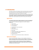
8: Troubleshooting and Contact Information This chapter discusses how you can diagnose and fix errors quickly without having to contact a dealer or Lantronix. It helps to connect a terminal to the serial port while diagnosing an error so you can view summary messages that may display. When troubleshooting, always ensure that the physical connections (power cable, network cable, and serial cable) are secure. Note: Some unexplained errors might be caused by duplicate IP addresses on the network.
Troubleshooting and Contact Information UDS10/UDS100 User Guide Table 8-1.
UDS10/UDS100 User Guide Troubleshooting and Contact Information Problem/Message Reason Solution When you Telnet to port 1 to assign an IP address to the UDS, the Telnet window does not respond for a long time. You may have entered the hardware address incorrectly with the ARP command. Confirm that the hardware address that you entered with the ARP command is correct. The hardware address may only include numbers 0-9 and letters A-F.
Troubleshooting and Contact Information UDS10/UDS100 User Guide Problem/Message Reason Solution The UDS is not communicating with the serial device attached to the UDS. The most likely reason is the wrong serial cable or serial settings were chosen. Make sure that you are using the correct serial cable. The UDS serial port is just like a modem serial port (DCE). The serial settings for the serial device and the UDS must match.
UDS10/UDS100 User Guide Troubleshooting and Contact Information Problem/Message Reason Solution You are using the correct serial cable, and the UDS is set up correctly, but you are not communicating with your device attached to the UDS across the network. If you are sure that the serial cable is correct, then you may not be connecting to the correct socket of the UDS. You can check to see whether there is a socket connection to or from the UDS by looking at the Status LED.
Troubleshooting and Contact Information UDS10/UDS100 User Guide When you report a problem, please provide the following information: Your name, and your company name, address, and phone number Lantronix UDS model number Lantronix UDS serial number Software version (on the first screen shown when you Telnet to port 9999) Description of the problem Debug report (stack dump), if applicable Status of the unit when the problem occurred (please try to include information on user and n
9: Connections and Pinouts Serial Port The UDS has a female DCE DB25 serial port that supports RS-232 and RS-485/422 serial standards (software selectable) up to 115 Kbps. Figure 9-1. Serial Interface Serial Connector Pinouts The unit’s female DB25 connector provides an RS-232C, RS-485, or RS-422 DCE serial port. The default serial port settings are 9600 baud, 8 bits, no parity, and 1 stop bit.
Connections and Pinouts UDS10/UDS100 User Guide Figure 9-2. DB25 Female DCE Interface RS232 Figure 9-3.
UDS10/UDS100 User Guide Connectons and Pinouts Null-Modem Cable When attaching the DB9 of the UDS to the DB9 com port on a PC, use a null-modem cable (Lantronix Part No. 500-163). The figure below shows the pinouts for a DB9 to DB9 null-modem cable. To configure the UDS using the DB9 serial port, you only need to pinout the TXD, RXD, and GND signals. Figure 9-4. Null-Modem Cable (Lantronix Part No. 500-163) Network Port The unit's back panel contains a power plug and an RJ45 (10/100) Ethernet port.
Connections and Pinouts UDS10/UDS100 User Guide Ethernet Connector Pinouts The UDS10 supports 10 Mbps half-duplex Ethernet through an RJ45 connector. The UDS100 supports 100 Mbps half or full duplex Ethernet through an RJ45 connector. Figure 9-6.
10: Technical Specifications UDS10 Technical Specifications CPU, Memory x86 CPU, 25MHz clock, 128kByte RAM Serial Interface Female DB25 connector (DCE pinout) Speed software selectable (300 to 115 kBaud) Software selectable RS-232C or RS-422/485 Network Interface 10 Mbps RJ45 Ethernet Power Supply External adapter included 120 VAC USA 100 - 240 VAC Universal with regional connectors Power Input 9-30 VDC or 9-24 VAC (1W maximum) Dimensions Height: 2.3 cm (0.9 in) Width: 6.4 cm (2.5 in) Depth: 9.
Technical Specifications UDS10/UDS100 User Guide UDS100 Technical Specifications CPU, Memory Lantronix DSTni-LX 186 CPU, 48 MHz 1 MByte FLASH ROM 256 Kbytes zero wait state RAM Serial Interface Female DB25 connector (DCE pinout) Speed software selectable (300 to 115 kBaud) Software selectable RS-232C or RS-422/485 Network Interface 10/100 RJ45 Ethernet Power Supply External adapter included 120 VAC USA 100 - 240 VAC Universal with regional connectors Power Input 9-30 VDC or 9-24 VAC (1W maximum) D
A: Alternative Ways to Assign an IP Address Earlier chapters describe how to assign a static IP address using DeviceInstaller, Web Manager, and Setup Mode (through a Telnet or serial connection). This section covers other methods for assigning an IP address over the network. DHCP The unit ships with a default IP address of 0.0.0.0, which automatically enables DHCP. If a DHCP server exists on the network, it provides the unit with an IP address, gateway address, and subnet mask when the unit boots up.
Alternative Ways to Assign an IP Address UDS10/UDS100 User Guide BOOTP Similar to DHCP, but for smaller networks. Automatically assigns the IP address for a specific duration of time. ARP and Telnet If the unit has no IP address, you can use Address Resolution Protocol (ARP) method from UNIX and Windows-based systems to assign a temporary IP address. To assign a temporary IP address: 1.
B: Binary to Hexadecimal Conversions Many of the unit’s configuration procedures require you to assemble a series of options (represented as bits) into a complete command (represented as a byte). The resulting binary value must be converted to a hexadecimal representation. Use this chapter to learn how to convert binary values to hexadecimals or to look up values in the tables of configuration options in hexadecimal notation.
Binary to Hexadecimal Conversions UDS10/UDS100 User Guide Scientific Calculator Another simple way to convert binary to hexadecimals is to use a scientific calculator, such as the one available on Windows’ operating systems. For example: 1. On the Windows’ Start menu, click ProgramsÆAccessoriesÆCalculator. 2. On the View menu, select Scientific. The scientific calculator displays. 3. Click Bin (Binary), and type the number you want to convert. 4. Click Hex. The hexadecimal value displays.
UDS10/UDS100 User Guide Binary to Hexadecimal Conversions Connect Mode Options Note: Character response codes are C=conn, D=disconn, N=unreachable Connect Mode Options Accept Incoming Connections Serial Response Upon Connection Active Connection Startup Hostlist Hex Never None (quiet) No active startup N/A Never None (quiet) Any character 1 Never None (quiet) Active DTR 2 Never None (quiet) CR (0x0D) 3 Never None (quiet) Manual connection 4 Never None (quiet) Autostart 5 Never
Binary to Hexadecimal Conversions UDS10/UDS100 User Guide Connect Mode Options Accept Incoming Connections Serial Response Upon Connection Active Connection Startup Hostlist Hex Unconditionally None (quiet) Autostart C5 Unconditionally None (quiet) UDP CC Unconditionally Character No active startup D0 Unconditionally Character Any character D1 Unconditionally Character Active DTR D2 Unconditionally Character CR (0x0D) D3 Unconditionally Character Manual connection D4 Uncon
UDS10/UDS100 User Guide Binary to Hexadecimal Conversions Connect Mode Options Accept Incoming Connections Serial Response Upon Connection Active Connection Startup Hostlist Hex Unconditionally None (quiet) No active startup Hostlist Unconditionally None (quiet) Any character Hostlist E1 Unconditionally None (quiet) Active DTR Hostlist E2 N/A Unconditionally None (quiet) CR (0x0D) Hostlist E3 Unconditionally None (quiet) Manual connection Hostlist N/A Unconditionally None (qu
Binary to Hexadecimal Conversions UDS10/UDS100 User Guide Disconnect Mode Options Disconnect Mode Options Disconnect Telnet Mode Channel with DTR and (port) Drop Terminal Password Type Setup 0 10 Enable Enable 20 Enable Enable Enable 30 Enable 40 Enable Enable 50 Enable Enable 60 Enable Enable Enable 70 Enable 80 Enable Enable 90 Enable Enable Enable Enable Enable Enable Enable Enable Enable Enable Enable Enable Enable Enable Enable Enable Enable Enable Enable En
UDS10/UDS100 User Guide Binary to Hexadecimal Conversions Disconnect Mode Options Disconnect Telnet Mode Channel with DTR and (port) Drop Terminal Password Type Setup Enable Enable Enable Enable Enable Enable Enable Enable 88 98 Enable Enable Enable Enable Enable Enable Enable B8 C8 Disable D8 Disable Enable E8 Enable F8 Disable Enable Disable Enable Enable 29 Disable Enable Enable 39 Disable Enable Disable Enable Disable Enable Enable 69 Disable Enable Enable 7
Binary to Hexadecimal Conversions UDS10/UDS100 User Guide Flush Mode Options Flush Mode Options Serial to Network Network to Serial Clear input buffer upon: Clear output buffer upon: Alternate Packing Algorithm Hex None 0 Active connection 10 Passive connection 20 Active connection Passive connection 30 Disconnect 40 Active connection Disconnect 50 Passive connection Disconnect 60 Active connection Passive connection Disconnect 70 Enable 80 Active connection Enable 90 Passive conn
UDS10/UDS100 User Guide Binary to Hexadecimal Conversions Flush Mode Options Serial to Network Network to Serial Alternate Packing Algorithm Hex Enable B1 Clear input buffer upon: Clear output buffer upon: Active connection Passive connection Active connection Disconnect Active connection Enable C1 Active connection Disconnect Active connection Enable D1 Passive connection Disconnect Active connection Enable E1 Active connection Passive connection Disconnect Active connection Enable
Binary to Hexadecimal Conversions UDS10/UDS100 User Guide Flush Mode Options Serial to Network Network to Serial Alternate Packing Algorithm Hex Clear input buffer upon: Clear output buffer upon: Active connection Disconnect Active connection Passive connection 53 Passive connection Disconnect Active connection Passive connection 63 Active connection Passive connection Disconnect Active connection Passive connection 73 Active connection Passive connection Enable 83 Active connection Acti
UDS10/UDS100 User Guide Binary to Hexadecimal Conversions Flush Mode Options Serial to Network Network to Serial Alternate Packing Algorithm Hex Clear input buffer upon: Clear output buffer upon: Passive connection Disconnect Disconnect Enable E4 Active connection Passive connection Disconnect Disconnect Enable F4 Active connection Disconnect 5 Active connection Active connection Disconnect 15 Passive connection Active connection Disconnect 25 Active connection Passive connection Act
Binary to Hexadecimal Conversions UDS10/UDS100 User Guide Flush Mode Options Serial to Network Network to Serial Alternate Packing Algorithm Hex Clear input buffer upon: Clear output buffer upon: Disconnect Passive connection Disconnect 46 Active connection Disconnect Passive connection Disconnect 56 Passive connection Disconnect Passive connection Disconnect 66 Active connection Passive connection Disconnect Passive connection Disconnect 76 Passive connection Disconnect Enable 86 Acti
UDS10/UDS100 User Guide Binary to Hexadecimal Conversions Flush Mode Options Serial to Network Network to Serial Clear input buffer upon: Clear output buffer upon: Active connection Passive connection Disconnect Active connection Passive connection Disconnect Alternate Packing Algorithm Hex 77 Active connection Passive connection Disconnect Enable 87 Active connection Active connection Passive connection Disconnect Enable 97 Passive connection Active connection Passive connection Disconnect
Binary to Hexadecimal Conversions UDS10/UDS100 User Guide Interface Mode Options Interface Mode Options Interface Bits Parity Stop Hex Bits RS-232C 7 No RS-232C 7 No 2 C8 RS-232C 7 Even 1 78 RS-232C 7 Even 2 F8 RS-232C 7 Odd 1 58 RS-232C 7 Odd 2 D8 RS-232C 8 No 1 4C RS-232C 8 No 2 CC RS-232C 8 Even 1 7C RS-232C 8 Even 2 FC RS-232C 8 Odd 1 5C RS-232C 8 Odd 2 DC RS-422/485 7 No 1 49 RS-422/485 7 No 2 C9 RS-422/485 7 Even 1 79 1 48
UDS10/UDS100 User Guide Binary to Hexadecimal Conversions Pack Control Options Pack Control Options Sendcharacter Trailing Defined by a: Characters Idle Time Force Transmit: Send Immediately after Sendcharacter Hex 1-Byte Sequence No 12ms 0 1-Byte Sequence No 52ms 1 1-Byte Sequence No 250ms 2 1-Byte Sequence No 5sec 3 1-Byte Sequence 1 12ms 4 1-Byte Sequence 1 52ms 5 1-Byte Sequence 1 250ms 6 1-Byte Sequence 1 5sec 7 1-Byte Sequence 2 12ms 8 1-Byte Sequence 2 52ms
Binary to Hexadecimal Conversions Pack Control Options Sendcharacter Trailing Defined by a: Characters UDS10/UDS100 User Guide Idle Time Force Transmit: Send Immediately after Sendcharacter Hex 2-Byte Sequence No 5sec Yes 33 2-Byte Sequence 1 12ms Yes 34 2-Byte Sequence 1 52ms Yes 35 2-Byte Sequence 1 250ms Yes 36 2-Byte Sequence 1 5sec Yes 37 2-Byte Sequence 2 12ms Yes 38 2-Byte Sequence 2 52ms Yes 39 2-Byte Sequence 2 250ms Yes 3A 2-Byte Sequence 2 5sec Yes
Declaration of Conformity (according to ISO/IEC Guide 22 and EN 45014) Manufacturer’s Name & Address: Lantronix 15353 Barranca Parkway, Irvine, CA 92618 USA Declares that the following product: Product Name Model: Device Servers UDS10 and UDS100 Conforms to the following standards or other normative documents: Safety: EN60950:1992+A1, A2, A3, A4, A11 Electromagnetic Emissions: EN55022: 1994 (IEC/CSPIR22: 1993) FCC Part 15, Subpart B, Class B IEC 1000-3-2/A14: 2000 IEC 1000-3-3: 1994 Electromagnetic Immuni
Warranty Lantronix warrants each Lantronix product to be free from defects in material and workmanship for a period of TWO YEARS after the date of shipment. During this period, if a customer is unable to resolve a product problem and Lantronix Technical Support determines the product is defective, a Return Material Authorization (RMA) will be issued. Following receipt of an RMA number, the customer shall return the product to Lantronix, freight prepaid.
Index Alternative methods of assigning, 57 Assigning by DeviceInstaller, 16 Assigning by Web Manager, 20 Assigning in Setup Mode, 24 Factory default, 15 Remote, 32 Requirement, 15 Searching for on the network, 17 Label, 13 LEDs, 45 MAC address, 13 Modem emulation, 12 Modem Mode, 30 Monitor Mode Accessing, 43 Commands, 44 Network class, 16 Null-modem cable, 53 Pack control, 34 Password Channel (Port), 35 Enhanced security, 37 Pinouts, 19, 51 Port 9999 for Setup Mode access, 27 Disabling Echo, 37 Number, 27 P
Index UDS10/UDS100 User Guide Technical specifications UDS10, 55 UDS100, 56 Technical Support, 49 Telnet Configuration password, 25 Password, 20 Terminal type, 35 TFTP, 40 Troubleshooting, 45 UDS settings configuration window, 19 Updating firmware, 39 Warranty, 76 Web browser, 18 Web Manager Configuration using, 19 Disabling configuration by, 37 Login, 17 Settings, 26 Serial tunneling Example, 10 Tutorial, 19 Server properties, 20 Setup Mode Accessing by Serial Port, 23 Accessing using Telnet, 22 Disablin