
User's Manual


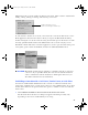


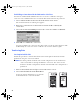
Table Of Contents
- Copyright © 2005 LifeScan, Inc. All rights reserved. No part of this publication may be reproduced, transmitted, transcribed, st...
- Disclaimer LifeScan reserves the right to change its products and services at any time to incorporate the latest technological developments. This guide is subject to change without notice.
- Trademarks OneTouch, DataLink, SureStepFlexx, and SureStepPro are registered trademarks of LifeScan, Inc.
- MeterLink is a trademark of LifeScan, Inc.
- Lantronix is a registered trademark of Lantronix.
- Windows is a registered trademark of Microsoft Corporation.
- InstallAnywhere is a registered trademark of Zero G Software, Inc.
- DataLink® Connection Overview 1
- DataLink Sync Configuration 4
- Modem-to-Modem Configuration 9
- Serial Server/Client-to-Ethernet Configuration 10
- Serial Server/Client-to-Ethernet Configuration Using Modems 11
- Terminal Server-to-Ethernet Configuration Using Multiple Receiving Modems 13
- Connecting to the Workstation 14
- Wireless Communication 16
- Establishing Connectivity Using MeterLink™ Software 20
- Transferring Data 26
- Troubleshooting 31
- Specifications 36
- Glossary 38
- Index 42
- Table of Contents
- Direct Connection
- Modem Configuration
- Network Configuration
- Using This Guide
- Installing DataLink Sync Software on a PC Server
- 1 Install DataLink Sync on the workstation. Follow the instructions provided with the DataLink Sync Installation CD.
- 2 From the PC where you wish to install DataLink Sync software, use the Search/ Find feature to search for the DataLink workstation computer on the network.
- 3 Enter the name of the DataLink workstation. The default name should be LFS_DATALINK or LFS-DATALINK.
- 4 Locate and open the DataLink Sync directory on the C drive.
- 5 Double-click install.htm.
- 6 Click Start Installer for Windows.
- 7 Click Next in the Introduction window.
- 8 Click Install to install DataLink Sync software in the default directory (C:/Program Files/LifeScan/DataLink Sync). Or, if you wish to install the program in another location, click Choose and select a new directory.
- 9 Click Done in the Install Complete window.
- 10 Close the browser window.
- Connecting a DataLink Connection Module to the PC Server
- Using DataLink Sync Software
- Connecting a DataLink Connection Module to a Sending Modem
- 1 Connect the 3-pin plug of the connection module power cord to the receptacle on the AC adapter. Then, plug the AC adapter into an AC power outlet.
- 2 Set the switches on the back of the modem as follows:
- 1
- 2
- 3
- 4
- 5
- 6
- 7
- 8
- up
- up
- down
- up
- down
- up
- down
- down
- 3 Connect the power cord from the modem to an AC power outlet.
- 4 Connect a phone cable from the modem to an analog phone jack.
- 5 Connect a phone cable from the connection module to the modem connector. Then, connect the modem connector to the modem. If th...
- 6 Turn on the modem.
- Serial Server/Client-to-Ethernet Configuration
- Connecting a DataLink Connection Module to a Serial Server/Client
- 1 Connect the 3-pin plug of the connection module power cord to the receptacle on the AC adapter. Then, plug the AC adapter into an AC power outlet.
- 2 Connect a phone cable between the connection module and the serial server connector. Then, connect the serial server connector...
- 3 Connect the power cord from the serial server/client to an AC power outlet.
- 4 Connect the network patch cable from the serial server/client to the network jack or hub.
- Serial Server/Client-to-Ethernet Configuration Using Modems
- Connecting a Receiving Modem to a Serial Server/Client
- 1 Set the switches on the back of the modem as follows:
- 1
- 2
- 3
- 4
- 5
- 6
- 7
- 8
- down
- up
- up
- down
- up
- up
- down
- up
- 2 Connect the power cord from the modem to an AC power outlet.
- 3 Connect a phone cable from the modem to an analog phone jack. The jack must be for a dedicated analog phone line.
- 4 Connect the power cord from the serial server/client to an AC power outlet.
- 5 Connect the network patch cable from the serial server/client to the network jack or hub.
- 6 Connect the modem-to-serial server cable between the serial server/client and modem.
- 7 Turn on the modem.
- Terminal Server-to-Ethernet Configuration Using Multiple Receiving Modems
- Connecting a Receiving Modem to a Terminal Server
- 1 Set the switches on the back of the modem as follows:
- 1
- 2
- 3
- 4
- 5
- 6
- 7
- 8
- down
- up
- up
- down
- up
- up
- down
- up
- 2 Connect the power cord from the modem to an AC power outlet.
- 3 Connect a phone cable from the modem to an analog phone jack. The jack must be for a dedicated analog phone line.
- 4 Connect the network patch cable from the terminal server to the terminal server connector. Then, connect the terminal server connector to the modem.
- 5 Connect the power cord from the terminal server to an AC power outlet.
- 6 Connect the network patch cable from the terminal server to the network jack or hub.
- 7 Turn on the modem and terminal server.
- Connecting to the Workstation
- Connecting a DataLink Connection Module to the Workstation
- 1 Connect the 3-pin plug of the connection module power cord to the receptacle on the AC adapter. Then, plug the AC adapter into an AC power outlet. If you’re connecting a SureStepFlexx meter to the workstation using a serial cable, skip this step.
- 2 Connect a phone cable from the connection module to the serial port connector. Then, connect the serial port connector to the ...
- 3 If applicable, connect the network patch cable from the workstation to the network jack.
- 4 Turn on the workstation.
- Connecting a Receiving Modem to the Workstation
- 1 Set the switches on the back of the modem as follows:
- 1
- 2
- 3
- 4
- 5
- 6
- 7
- 8
- down
- up
- up
- down
- up
- up
- down
- up
- 2 Connect the power cord from the modem to an AC power outlet.
- 3 Connect a phone cable from the modem to an analog phone jack. The phone jack must be for a dedicated analog phone line.
- 4 Connect the serial modem cable from the modem to the serial port on the workstation.
- 5 If applicable, connect the network patch cable from the workstation to the network jack.
- 6 Turn on the modem and workstation.
- Wireless Communication
- Setting Up the Wireless Unit
- 1 Connect a phone cable to the serial port connector. Then, connect the serial port connector to the workstation’s serial port.
- 2 Open a HyperTerminal session in Windows.
- 3 Click Restore Defaults on the Port Settings screen. The COM properties for the port should be:
- 4 Connect the charger to the wireless unit. Then, plug the charger into an AC power outlet.
- 5 While holding down the x key on the keyboard, connect the other end of the phone cable (from step 1) to the Setup jack on the side of the wireless unit.
- 6 Press Enter when prompted.
- Configuring Network Parameters and Channel Settings
- For a Static IP
- For DHCP
- Charging the Wireless Unit
- Cleaning the Wireless Unit
- MeterLink Application Window
- Establishing a Connection with a Serial Server, Terminal Server, or Serial Client
- Establishing a Connection with a PC Server/Client
- Establishing a Connection with the Workstation Serial Port
- SureStepPro Bedside Unit
- SureStepFlexx Meter
- MeterLink Event Errors
- Meter Error Messages
- Wireless Unit LED Error Conditions
- Ethernet Connection from the PC Server
- Ethernet Connection from the Meter Location
- Ethernet Connection from the Workstation
- Connection Module
- Wireless Unit

17
• Flow Control = None
4 Connect the charger to the wireless unit. Then, plug the charger into an
AC power outlet.
5 While holding down the x key on the keyboard, connect the other end of the
phone cable (from step 1) to the Setup jack on the side of the wireless unit.
6 Press Enter when prompted.
Figure 9 Setting up the OneTouch DataLink Wireless unit
Configuring Network Parameters and Channel Settings
Perform the following steps with the wireless unit still connected to the computer.
1 From the Change Setup menu, select option 0 and press Enter.
2 Continue with the appropriate instructions below depending on whether you
are using static IP addresses or DHCP.
For a Static IP
• Enter the IP address for the wireless unit.
• Enter the Gateway IP address.
• Enter 8 for the Netmask: Number of Bits for Host Port.
• Change the default Telnet password, if you wish.
For DHCP
• Enter 0 for the IP address fields.
• If not supplied by the DHCP Server, enter the Gateway IP address.
• Enter 8 for the Netmask: Number of Bits for Host Port.
• Change the default Telnet password, if you wish.
• Change the DHCP device name, if you wish.
■
NOTE: The DHCP name defaults to CXXXXXX, where XXXXXX is the last six
digits of the MAC address for the wireless unit.
ethernet.book Page 17 Friday, December 2, 2005 4:28 PM