
User's Manual

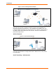
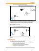
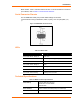

Table Of Contents
- List of Tables
- List of Figures
- Using This Guide
- Introduction
- Quick Start
- Configuration via Serial Mode or Telnet Port
- Configuration using Web-Manager
- Configuration using DeviceInstaller
- Monitoring the Network
- Updating Firmware
- Troubleshooting

WiBox™ User Guide 17
3
3
:
:
Q
Q
u
u
i
i
c
c
k
k
S
S
t
t
a
a
r
r
t
t
This chapter describes the installation procedure for the WiBox.
Required Information
Hardware Address
Take note of the unit’s hardware address (also known as MAC address). It is on the
product label, in the format: 00-20-4a-XX-XX-XX, where the XXs are unique numbers
assigned to the product.
Hardware Address: 00-20-4a-_____-_____-_____
IP Address
The WiBox must have a unique IP address on the network. The systems
administrator generally provides the IP address, subnet mask, and gateway.
IP Address: _______ _______ _______ _______
Subnet Mask: _______ _______ _______ _______
Gateway: _______ _______ _______ _______
WLAN Settings:
Before the WiBox can communicate on an 802.11b wireless network, the WLAN
settings must match the wireless network. By default, the WiBox is set to Ad-Hoc
network mode and its wireless Network Name (SSID) is “LTRX_IBSS”.
Installing the WiBox
Complete the following steps to connect and initially configure the WiBox. Initial
configuration is done using Serial Mode.
INSERT Wibox diagram Figure x.x
1. Connect one end of the supplied DB9F – DB9M null modem serial cable to the
Wibox’s serial port 1.
2. Connect the other end of the DB9 serial cable to a terminal or a PC’s serial COM
port.
3. On the PC, open a terminal emulation application (e.g. HyperTerminal). The
default serial settings are: 9600 baud, 8 bits, not parity, 1 stop bit and no flow
control(9600, 8, N, 1).
4. Enter Setup Mode by simultaneously connecting the power supply and holding
down the x key.