
User's Manual
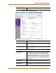
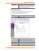


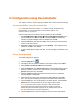
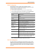
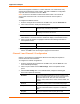
Table Of Contents
- List of Tables
- List of Figures
- Using This Guide
- Introduction
- Quick Start
- Configuration via Serial Mode or Telnet Port
- Configuration using Web-Manager
- Configuration using DeviceInstaller
- Monitoring the Network
- Updating Firmware
- Troubleshooting

Application Examples
4 WiBox™ User Guide
The host list supports a minimum of 1 and a maximum of 12 entries. Each entry
contains an IP address and a port number. This field is available for configuration
only when Active Connection is not set to None.
Note: The host list is disabled for Manual and Modem Mode. The unit will not
accept a data connection from a remote device when the host list option is
enabled.
To configure the WiBox’s host list:
1. From the Configure Device window for the WiBox unit, click the Advanced tab.
2. In the Host List section, modify the following fields:
Retry Counter Enter the value for the number of times the WiBox should
attempt to retry connecting to the host list.
Retry Timeout Enter the duration (in seconds) the WiBox should abandon
attempting connection to the host list.
3. Click the “…” next to the Host List field to open the HostListEntry Collection
Editor Window. The list of host list IP addresses display in the Members section.
4. Click on a host list member to highlight it and enter the following information in
the Properties section:
Host
Enter or modify the Host’s IP address.
Port
Enter the port on which the Host’s IP address resides.
5. Click Apply to apply the changes immediately to the WiBox and automatically
reboot. Click OK to save the changes to apply at the next reboot.
Channel 1 and Channel 2 Configuration
Channel 1 and Channel 2 configurations define how the serial port responds to
network and serial communications.
To configure the channel configurations:
1. From the Configure Device window for the WiBox unit, click the Ports tab. The
list of available ports display.
2. Click on a port number and click Edit Settings. The Port Properties window
opens.
3. Click the Port Settings tab. In the available fields, change the following pull
down menu options as necessary:
Baud Rate The unit and attached serial device, such as a modem, must
agree on a speed or baud rate to use for the serial connection.
Valid baud rates are 300, 600, 1200, 2400, 4800, 9600
(default), 19200, 38400, 57600, 115200, 230400, 460800, and
921600.
Data bits
Indicates the number of bits in a transmitted data package.
Parity Refers to the checking whether data has been lost or written
over when transmitted between computers. The default is
None.
Stop bits The stop bit follows the data and parity bits in serial