
Product Info


LP
WA Module Series
BG95 Series Hardware Design
BG95_S
eries_Hardware_Design 45 / 106
R
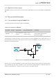
ESET_N
S2
Close to S2
TVS
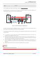
Figur
e 12: Reference Circuit of RESET_N by Using Button
Please a
ssure that there is no large capacitance on RESET_N pin.
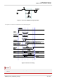
3.8. PON_
TRIG Interface
BG95
provides one PON_TRIG pin which is used to wake up the module from PSM. When the pin detects
a rising edge, the module is woken up from PSM.
Table 10: Pin Definition of PON_TRIG Interface
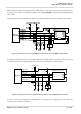
A reference circuit is shown in the following figure.
Pin N
ame
Pin N
o.
I/
O
De
scription
Com
ment
PON
_TRIG 96 DI Wake up the module from PSM
Rising-edge triggered.
Pulled-down by default.
1.8 V power domain.
NOT
E