
Product Info

LP
WA Module Series
BG95 Series Hardware Design
BG95_S
eries_Hardware_Design 56 / 106
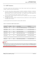
Tab
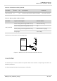
le 20: Pin Definition of STATUS
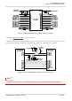
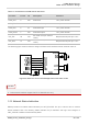
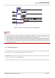
The following figure shows a reference circuit of STATUS.
Figure 22: Reference Design of STATUS
3.15. Be
haviors of MAIN_RI
A
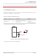
T+QCFG="risignaltype","physical" command can be used to configure MAIN_RI pin behavior.
No matter on which port the URC is presented, the URC will trigger the behavior of MAIN_RI pin. The
default behaviors of MAIN_RI pin are shown as below.
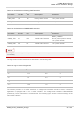
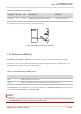
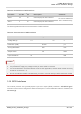
Table 21: Default Behaviors of MAIN_RI Pin
The default MAIN_RI pin behaviors can be configured flexibly by AT+QCFG="urc/ri/ring" command. For
more details about AT+QCFG*, see document [2].
1. U
RC can be outputted from UART port, USB AT port and USB modem port, through configuration via
A
T+QURCCFG command. The default port is USB AT port.
Pin N
ame
Pin N
o.
I/
O
De
scription
Com
ment
STAT
US 20 DO Module operation status indication 1.8 V power domain
State Re
sponse
Idle MAIN
_RI keeps in high level.
U
RC MAIN_RI outputs 120 ms low pulse when a new URC returns.
NOTES