
Product Info

LP
WA Module Series
BG95 Series Hardware Design
BG95_S
eries_Hardware_Design 61 / 106
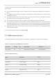
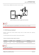
3.19. GRF
C Interfaces
The
module provides two generic RF control interfaces for the control of external antenna tuners.
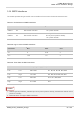
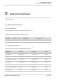
Table 27: Pin Definition of GRFC Interfaces
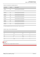
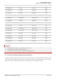
Table 28: Logic Levels of GRFC Interfaces
Table 29: Truth Table of GRFC Interfaces
1. GRFC2 (p
in 84) is a BOOT_CONFIG pin. Never pull it up before startup, otherwise the module cannot
power on normally.
2. BG95-M
4 does not support GRFC interfaces.
Pin N
ame
Pin N
o.
De
scription
Com
ments
GRFC1 83 Gener
ic RF controller 1.8 V power domain.
GRFC2 84 Gener
ic RF controller
BOOT_CONFIG.
Do not pull it up before startup.
1.8 V power domain.
Param
eter
M
in.
M
ax.
Un
it
V
OL
0 0.45 V
V
OH
1.35 1.8 V
GRF
C1 Level
GRFC2 Lev
el
Freq
uency Range (MHz)
Band
Low Low 880–2200 B1, B2, B3, B4, B8, B25, B66
Low High 791–894 B5,
B18, B19, B20, B26, B27
High Low 698–803 B12,
B13, B28, B85
High High 617–698 B71
NOT
ES