
Product Info

LP
WA Module Series
BG95 Series Hardware Design
BG95_S
eries_Hardware_Design 69 / 106
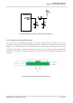
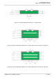
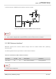
A reference design of GNSS antenna interface is shown as below.
Figure 30: Reference Circuit of GNSS Antenna Interface
1. An exter
nal LDO can be selected to supply power according to the active antenna requirement.
2. If t
he module is designed with a passive antenna, then the VDD circuit is not needed.
5.3. Wi-Fi
Antenna Interface*
BG95-M
F supports Wi-Fi antenna interface through which the module realizes Wi-Fi positioning
(receiving only).
The following tables show the pin definition of Wi-Fi antenna interface.
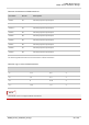
Table 35: Pin Definition of Wi-Fi Antenna Interface
“*
” means under development.
Pin Name Pin No. I/O Description Comment
ANT_WIFI 56 AI Wi-Fi antenna interface 50 Ω impedance
NOT
ES
NOT
E