
Data Sheet
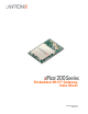


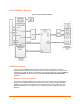
Table Of Contents
- Table of Contents
- List of Figures
- List of Tables
- 1: Functional Description
- 2: Hardware and Software Description
- xPico 200 Block Diagram
- Software Features
- Network Co-Processor Mode
- Wireless Microcontroller Mode
- TruPort Serial
- TruPort Socket
- Ethernet to Wi-Fi Bridge
- Concurrent Soft AP and Client Mode
- Enterprise Wi-Fi Security (802.11i, 802.1X/EAP)
- InfiniShield Security
- Wi-Fi Connection Profiles
- Configuration and Management Interface
- Reliable Firmware Over-The-Air (FOTA) Updates
- Power Management
- Pre-integration with MACH10 Platform
- Remote Gateway Management with Lantronix Gateway Central
- Integrated Bluetooth Classic and Bluetooth Low Energy Stacks (xPico 250)
- 3: Pin and Pad Definitions
- Note1: The current module supports an external 10/100 Mbps Ethernet PHY via the RMII interface.
- Note2: The logic IO pins are 3.3V tolerant.
- Note3: SMT Pins 67 to 75 are the ground pads under the module. These pads must be connected to ground. These pads also provide thermal relief for the module. It is recommended that multiple vias for each pad be used to connect the ground pads to t...
- Note 4: All unused IO pins may be left floating, except for the required straps on pins 17, 26, and 29.
- Note 5: Asterisk (*) indicates feature available in a future release. Contact your local sales representative for availability.
- Signal
- Pin
- Signal
- Pin
- Driver Strength
- Edge Connector Pin
- xPico 200 SMT Pin
- Primary Function
- Signal Name
- 4: Interfaces
- Edge Conn. Pin
- SMT Pin
- Description
- Pin Name
- Type A USB Host Conn. Pin
- Signal Requirement
- Edge Conn. Pin
- SMT Pin
- Description
- Pin Name
- Edge Conn. Pin
- SMT Pin
- Description
- Pin Name
- Edge Conn. Pin
- SMT Pin
- Description
- Pin Name
- Edge Connector Pin
- xPico 200 SMT Pin
- Reset State
- Description
- Pin Name
- Edge Connector Pin
- xPico 200 SMT Pin
- Description
- Pin Name
- 5: IEEE 802.11 Wireless Lan Specifications
- Description
- Feature
- China
- Japan
- New Zealand
- Australia
- Europe
- Canada
- FCC/USA
- Channel
- Frequency
- China
- Japan
- New Zealand
- Australia
- Europe
- Canada
- FCC/USA
- Channel
- Frequency
- China
- Japan
- New Zealand
- Australia
- Europe
- Canada
- FCC/USA
- Channel
- Frequency
- 6: Bluetooth Specifications
- Description
- Feature
- 7: Antenna Connection Options
- Approved Region
- Vendor Part Number
- Vendor
- Lantronix Part Number
- Peak Gain Typical
- Antenna Type
- Peak Gain Typical
- Antenna Type
- 8: Electrical Characteristics
- Units
- Max xPico 250
- Max xPico 240
- Typical xPico 250
- TypicalxPico 240
- Soft AP
- Power Mgmt
- Parameter
- Units
- Max xPico 250
- Max xPico 240
- Typical xPico 250
- Typical xPico 240
- Soft AP
- Power Mgmt
- Parameter
- Units
- Peak Current Typical
- Average Current
- Soft AP/Wi-Fi Client
- Power Mgmt
- Parameter
- Unit
- Tolerance
- TYP.
- Rate
- Mode
- Unit
- Max
- TYP.
- Min.
- Rate
- Mode
- Unit
- Maximum
- Maximum RF Receive Level
- Unit
- Maximum
- Maximum RF Receive Level
- Unit
- Maximum
- Maximum RF Receive Level
- Unit
- Max
- Rate
- Mode
- Typical
- Receiver Characteristics
- Unit
- Maximum
- Minimum
- Description
- Parameter
- Unit
- Maximum
- Minimum
- Description
- Parameter
- Unit
- Maximum
- Minimum
- Description
- Parameter
- 9: Package Description and Mechanical Footprint
- Description
- Category
- 10: Product Information Label
- Example
- Description
- Field
- 11: Compliance
- Labeling of the End Product
- Federal Communication Commission Interference Statement (xPico 240/250)
- Industry Canada Statement (xPico 240/250):
- Radiation Exposure Statement:
- Déclaration d'exposition aux radiations:
- This device is intended only for OEM integrators under the following conditions: (For module device use)
- Cet appareil est conçu uniquement pour les intégrateurs OEM dans les conditions suivantes: (Pour utilisation de dispositive module)
- IMPORTANT NOTE:
- NOTE IMPORTANTE:
- Plaque signalétique du produit final
- Manual Information To the End User
- Manuel d'information à l'utilisateur final
- Caution :
- Avertissement:
- RoHS, REACH, and WEEE Compliance Statement
- 12: Ordering Information
- Description
- Part Number
- Description
- Part Number
- Description
- Part Number

xPico
®
200 Series Embedded Wi-Fi
®
Gateway Data Sheet 4
List of Figures
Figure 2-1 xPico 240 Module Options ______________________________________________ 9
Figure 2-2 xPico 250 and xPico 270 Module Options __________________________________ 9
Figure 2-3 xPico 200 Block Diagram _____________________________________________ 10
Figure 2-4 Wi-Fi Integration Mode _______________________________________________ 11
Figure 2-5 Wireless Microcontroller Mode __________________________________________ 11
Figure 3-1 xPico 200 Edge Connector Pin & Signal Location ___________________________ 15
Figure 3-2 xPico 200 PCB Interface Pin & Signal Location _____________________________ 17
Figure 8-1 Reset Timing _______________________________________________________ 36
Figure 8-2 Reset to Defaults Timing ______________________________________________ 37
Figure 8-3 Wake Timing _______________________________________________________ 37
Figure 8-4 SPI Slave Timing ____________________________________________________ 38
Figure 8-5 SPI Master Timing ___________________________________________________ 39
Figure 9-1 xPico 200 Embedded Wi-Fi Gateway (On-Module Antenna) __________________ 41
Figure 9-2 xPico 200 Embedded Wi-Fi Gateway (Dual U.FL) __________________________ 41
Figure 9-3 Layout Footprint for xPico 200 Enterprise Wi-Fi IoT Module __________________ 42
Figure 9-4 xPico 200 Edge Connector Footprint Dimensions___________________________ 43
Figure 10-1 xPico 200 Module Label _____________________________________________ 44
Figure 11-1 EU Declaration of Conformity (xPico 240/250) ____________________________ 50