
Service Manual


TSM 20-399 Rev 0, Feb 2014 8 10W VHF Amplifier
3 MASK FILTER AND OUPTPUT
3.1 HELICAL RESONATOR BANDPASS FILTER
LARCAN bandpass filter implementations generally consist of a cascaded series of coupled resonators. Some use
helical resonators; essentially a self supporting high Q coil (the helix) mounted inside a metallic shield enclosure. One
end of the coil is solidly connected to the shield enclosure and the other end is open circuited except for a small
trimmer capacitance to ground. The dimensions of the coil are critical to the frequency of operation; the assembly
behaves as though it were a quarter wave coaxial transmission line resonator. Several sizes of coils and enclosures
are necessary to cover the desired frequency ranges.
Figure 4 indicates the generic assembly of a coupled helical resonator bandpass filter.
The referenced drawing in Figure 4 is a low band filter. The high band unit is laid out identically and appears almost the
same, except the high band helixes have fewer turns of coarser winding pitch and their shield enclosure dimensions
are somewhat smaller.
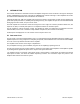
The desired response shape is presented as Figure 1 below, and the filter electrical equivalents are presented on the
next page as Figure 2. When we examine the assembly, and take capacitances into account, the equivalent circuit of a
helical resonator becomes simply a parallel resonant LC tank circuit having low (trimmer) capacitance and relatively
high inductance. Adjustment of the trimmer produces a change of capacitance and the trimmer's moveable slug is
shaped to appear as a shorted turn, which alters the inductance of the helix.
Matching from and to 50 ohm transmission lines is accomplished with taps on the input and output helixes.
Coupling between sections is electrically a bridged T network of capacitors and is made up of the small capacitance
between the free ends of the coils, controllable by the amount of capacitance to ground that is introduced by the
coupling adjustment screws; the coupling is maximum when the screws are backed out fully from the enclosure.
Shielding partitions placed inside the enclosure between helixes, produce fixed area apertures which affect the
coupling capacitance between helixes. Helix #3 in the Figure 4 drawing has taller partitions on both sides of it, giving
lower capacitance and less coupling than the others.
For system use, the tuning and coupling is adjusted for a flat topped response with steep sides, and the desired shape
is such that f
V
- 4.5 MHz and f
V
+ 9.0 MHz are both 30 dB down, but the carriers must be f
V
< 0.6 dB and f
A
< 0.7 dB
departure from flatness. Input and output return loss must be 20dB or better over the full 6 MHz bandwidth. These
sweep curves are shown below as Figure 1.
Figure 1 Bandpass Filter Response
There are nine screw adjustments and two I/O matching (with soldering iron) adjustments that need to be made
simultaneously, and all of them interact with each other. To make these adjustments properly, a network analyzer is
mandatory, and because this is an expensive piece of test equipment not likely to be available in the field, for this
reason we say the unit is not user-adjustable.
Our recommendation is to not adjust the filters at all.