
User Manual

class AB as a linear amplifier. This amplifier is capable of more than 50 watts
RF output when driven by the preamplifier in the present system, but uses the
identical dual FET device that is used in higher powered LARCAN transmitters.
The Sound/Aural signal of the transmitter is internally diplexed and corrected at
IF with the visual/vision signal within the exciter, and is amplified in common
with the visual/vision signal in the amplifier chain. Internal diplexing offers
the distinct advantage of lower cost.
The amplifier output is fed through the bandpass filter and the directional
coupler, which provides a small sample of forward and reflected output power for
AGC and VSWR supervisory functions. The transmitter output then passes to the
antenna.
TRANSMITTER CONTROL
The control circuitry in this solid state transmitter is simple. Interlocking in
the 30 W simply consists of jumpers (marked EXT1 and EXT2) but external patch
panel link switches, or RF switching auxiliary contacts, can be connected if
desired. This low power level generally needs no interlocking.
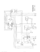
All control wiring of the transmitter passes through a control circuit board
(prefix 4), and facilities are provided on this board for telemetry, status, and
control connections to and from a remote control system.
The transmitter interlock wiring is also brought out on terminal block TB2.
External Interlocks 1 and 2 are all brought out on TB2 for connection as
required. Interlock 1 is provided here only for consistency with other LARCAN
transmitter designs in which this interlock is used with a fire alarm system to
shut off blowers.
In the 10 W, the control is so simple (just a single contactor) that either
Interlock 1 or 2 can be used. The cooling fan for the PA heatsink is wired
across the power supply output, therefore will operate whenever the supply is
energized. A thermostat is provided in the PA heatsink to open the interlock
chain should an unlikely overheating condition occur.
On site it is necessary to ensure that AC mains voltage within ±10% of nominal is
available, especially in sites where the voltage can often be extremely variable,
and/or failures are common. It is a good idea to log all voltage excursions in
such sites over a period of time, and then specify a suitable voltage regulator.
It may be necessary to specify a regulator capable of wide input range if site
voltage variations are extreme.
The amplifier's 48Vdc linear power supply (power-one type HD48-3-A) is rated
for 3A and is designed for operation from AC power line voltage variation of
+10%, -13%. The amplifier takes less than 240 VA.
The control's 12Vdc linear power supply is rated for 0.9A and is powered upon
application of AC into the unit.