
User Manual


VHF AMPLIFIER CHASSIS
PUB98-30 rev 0: Dec. 12, 1998
30-1
30W VHF Amplifier
Contents:
Part Topic Page
1 Chassis Description...........................................30-1
List of Figures:
Fig Title Drawing Reference
1 Chassis Assembly Diagram.............................40D2232 sht 1
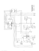
2 Wiring Diagram, Amplifier, AC Line to Neutral........30C1987 sht 1
3 `power-one' Power Supply Data.....................................
1. Amplifier Chassis Assembly 40D22328G1 through 40D2232G3: Figure 1.
The Amplifier Chassis consists of a standard 19" rack mounted 5¼" 3U enclosure
containing 2 linear power supplies, the amplifier heatsink assembly, the output
directional coupler, the bandpass filter (in most models), a cooling fan, a
control panel (meter and control board), an RF metering board, a line filter, and
an AC relay. Its basic part number is 40D2232.
Three frequency ranges are required to cover the entire VHF television spectrum,
thus there are three fundamental models of RF amplifier assemblies: for channels
2, 3, 4; channels 5, 6; and channels 7 - 13.
AC power input for the three Amplifier/ models is connected for system operation
from one line to neutral, most commonly from 115 volts AC single phase.
40D2232G1 is the chassis for a 30 watt amplifier for operation on channels 7
through 13 (174-216 MHz), it has a 150 watt power supply, and its AC
is connected line to neutral.
40D2232G2 is the chassis for a 30 watt Amplifier for operation on channels 2,
3, and 4 (54-72 MHz), it has a 150 watt power supply, and its AC is
connected line to neutral.
40D2232G3 is the chassis for a 30 watt Amplifier for operation on channels 5
and 6 (76-88 MHz), it has a 150 watt power supply, and its AC is
connected line to neutral.
Although we indicate NTSC frequency ranges, the amplifiers are capable of
frequency coverage outside the ranges cited, for CCIR systems B, D, etc.
transmitter applications in other regions worldwide.
Figure 1 is the fundamental assembly drawing of the chassis.
The heatsink cooling fan is a 48 volt DC "Muffin" model from Comair-Rotron; it is
Comment:
The footer date stamp
must be altered to agree with
the revision date.