
User's Manual


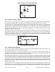
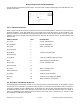
Table Of Contents
- 1 MXi005U AMPLIFIER
- 2 MXi CONTROLLER
- 2.1 MXi005U Control Board Assembly and Jumper settings
- 2.2 Remote Controls and the MXi005U Front Panel ON/OFF Button
- 2.3 External Remote Control Connections
- 2.4 External Transmitter Interlock
- 3 AMPLIFIER INSTALLATION AND STARTUP
- 4 TEST AND TROUBLESHOOTING
- 5 MAINTENANCE
- 6 TEST EQUIPMENT SETUP
- 7 SPECIFICATIONS

MXi005U OPERATIONS AND MAINTENANCE
can be connected to maximum 30 VDC output. The active (true) condition whether high or low will depend on the
specific status output.
Figure 6 Remote Status Outputs
2.3.4
2.4
External1 Interlock
There is a pair of terminals on the D-connector that is used for an external interlock to interface to any site alarms or
shutdown conditions. These pins would expect a dry contact that is closed when there is no error condition. This
External #1 interlock is in parallel with the two pin terminal block on the rear of the MXi transmitter chassis. The MXi
applied its own +12V to one side of this interlock (the Ext1+ line) and will sense this +12V on the other interlock side
(the Ext1- line).
REMOTE SIGNAL PIN# DESCRIPTION
RC_TXON 1 Control, Transmitter ON
RC_VSWRRst 2 Control, VSWR Reset
RS_TXON 3 Status, Transmitter ON
Spare [Unused] 4
RT_FwdPwr 5 Telemetry, Forward Power
Spare [Unused] 6
RT_CutBack 7 Telemetry, Cutback Voltage (1/2 Scale)
Ext1- 8 External Interlock, Normally Open
RC_TXOFF 9 Control, Transmitter OFF
Spare [Unused] 10
RS_TXErr 11 Status, Transmitter Error
Ground Reference 12 Ground Reference
RT_RflPwr 13 Telemetry, Reflected Power
RT_AGC 14 Telemetry, AGC Voltage (1/2 Scale)
Ext1+ 15 External Interlock, (+12V Armed)
EXTERNAL TRANSMITTER INTERLOCK
The MXi transmitter provides the customer a set of contacts where an external interlock can be applied to control
the ON state of the transmitter. The purpose of this interlock is to shut down the transmitter if there is sensed an
emergency condition (such as a building fire or smoke alarm) or it there is some RF output switch that is going to
be moved and the RF output of the transmitter needs to be shut off temporarily when the switch is in transit. If
there is no application for this interlock then the customer must insure that it is shorted out (i.e., closed) so that
the transmitter is enabled to be turned ON.
PUB06-76 Rev 2 July 18, 2007 06-76-6 MXi005U Operations and Maintenance