
Assembly Instructions


MXI1503-2004 CONTROL UNIT
PUB13-09 Rev 1 2
2 LCD GUI INTERFACE AND TOUCHPAD
The user interface to the transmitter is mainly accomplished with the front panel LCD that incorporates a touchpad as
an integral part of the unit. The touchpad consists of a thin membrane attached to the LCD surface which implements
a software-driven menu selection system. The LCD has the capability of displaying a number of different screens,
which are selected by the operator via the touchpad.
Each of the separate display screens (called Menus) is detailed in the following subsections along with their respective
touchpad menu options. When the MXi transmitter is first powered on or returns from an AC power outage, the LCD
displays a screen [Power Up Screen] that only shows for a few seconds and describes the particular transmitter that
this MXi is configured for. Note that there are no touchpad menu options on this screen, since it only displays for a
few seconds. After these seconds have passed, the MXi proceeds into the Main Menu screen described in the next
section.
2.1 MAIN SCREEN AND TOUCHPAD OPERATIONS
The Main Menu screen as shown below gives the operator all of the most pertinent values and status to verify the
operation of the transmitter. This screen is the one that is normally left displayed when no maintenance or diagnostic
checks are being performed. It is from this Main screen that all of the other submenu screens can be accessed. If the
operator has switched to another submenu, it is recommended that the LCD is returned to the Main screen, since this
shows an overview of the system operation.
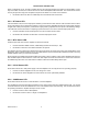
Figure 2 Main Menu Screen
The Main screen can be subdivided into four distinct sections, the main forward RF power at the top line, the
transmitter status on the second line, the individual subsystem status on the third line and the submenu options on the
fourth and last line.
The first line shows the forward RF power that the transmitter is currently generating. This is the power that is actually
being sent out to the antenna or system load. There are two elements that show the same information but in different
formats. The bar graph gives a graphic display of the RF power output level and is calibrated for 100% at the
transmitter’s rated output power. The bar graph will display up to 125% but it is not recommended that the operator
increase the power beyond the rated power without prior approval from LARCAN field service. When the power
exceeds 110%, the bar graph becomes more solid and darker in the area above 110% to indicate that an overpower
condition is present.
The same information is provided to the left of the bar graph in a three-digit display, which shows the current power
output. When calibrating or setting up the transmitter, this three-digit display value should be used as a reference for
the current transmitter power (not the bar graph). This display has a maximum value of 169% power when the
transmitter detectors are set up for a DC output of 4.0 at full power. This value is derived from the fact that the detector
can output a maximum of 5.0VDC to the telemetry circuits, which translates to an output power of 169%. Of course,
this is a maximum display value on the LCD fixed by circuit constraints and the operator should never be approaching
this type of power level with the transmitter. If a display of 169% is indeed shown, then either there is a problem with
the detector or the power of the transmitter is in fact exceeding 169% and should be attended to immediately.
The second line of the LCD shows the current state of the transmitter and any important errors that are current. This
line typically tells the operator if the transmitter has been asked to be in the ON state. The transmitter is placed in the
ON state either by the local front panel ON button or by a remote ON command. If the transmitter has been turned off
by the operator, the LCD reports that the transmitter is OFF normally (i.e., it was not due to an error).
If an error condition has occurred that caused the transmitter to shut down, the LCD displays that the transmitter is
OFF and then shows what the error condition is that has caused the shutdown. As an example, if the External#1
interlock is open, the LCD displays TX IS OFF, EXT1 INTERLOCK OPEN.