
Assembly Instructions


MXI1503-2004 OPERATIONS AND MAINTENANCE
PUB13-10 Rev 1 7
5 AMPLIFIER INSTALLATION AND STARTUP
The MXi Amplifier was fully tested at LARCAN before it was delivered. Under normal circumstances, the
transmitter can be fully operational with minimal setup when turned ON. However, a good practice is to take the
“start from scratch” approach, which means that one should take precautionary measures before the amplifier is
allowed to run at full rated power. These important steps will avoid any catastrophic failures at start-up. The
procedure described is essentially the same approach taken at the factory with a new and untested transmitter.
This also applies if there is a need to completely replace a major sub-assembly in the transmitter.
5.1 BEFORE APPLYING AC TO THE UNIT
Pay careful attention to items 1 to 3 before applying AC to the amplifier. These are initial steps that must be
observed and followed for proper and safe operation of the amplifier.
1. Termination
Ensure that the amplifier is properly terminated with a suitable load. This can be into a dummy load or into
the transmitter output system. A 50 Ohm, 1kW load with at least –20dB return loss (1.2 VSWR) is
recommended. Preferably, directional couplers with known coupling levels at the frequency of interest
should be connected at the input and output of the band-pass filter. These points are very useful in
determining absolute power levels and losses, and also for use as an RF sample for monitoring purposes.
See Figure 10 for a typical transmitter test equipment setup.
2. Interlocks
Interlocks must be connected to the amplifier to avoid damage to the equipment and to the output section.
The overall interlock is located on the rear panel of the Main Control chassis and it is labeled INT’K. If this
interlock is open, the +50V to each Amplifier will shut down, including the cooling fans.
3. Power At Minimum
Initially, the modulator’s output should be at minimum level.
5.2 APPLYING AC TO THE UNIT
Check that the AC going into Main AC Breaker ranges from 190-264VAC. If this is so, proceed to
applying power, otherwise, investigate the source of the problem.
Usually, once the AC is applied to the breakers and the breakers are in the on position, the Control Power
Supply turns ON and applies +12V to the Main Controller and the controller in each amplifier.
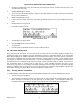
The Power-Up screen will be displayed on the LCD, followed immediately by the Main Menu.
Figure 3 Main Menu
5.3 BEFORE TURNING THE AMPLIFIER ON
From the Main Menu, the status of the amplifier is displayed and shows if the amplifier is ready for operation.
Status legends, when lit, such as the INTK (INTERLOCK), usually signify OK conditions and that the transmitter is
ready to be switched ON.
Check that all of the following conditions are met:
1. Modulator and up-converter, or Channel Processor is ready.