
Assembly Instructions
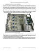

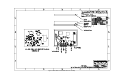

Table Of Contents
MXi501/1002U POWER AMPLIFIER HEATSINK ASSEMBLY
5 FIVE-WAY SPLITTER/FIVE-WAY COMBINER
Drawing reference: Figure 8 to Figure 11
The splitter utilizes a combination of hybrid 4-port quadrature (90° phase difference) couplers that require
terminations on the 4
th
port. The termination maintains isolation between the two output ports of the individual
hybrids. The input section is a 2.22dB hybrid which feeds a 3dB hybrid from one output port and a 1.76dB hybrid
from the other port. One output of the 1.76dB hybrid further feeds another 3dB hybrid.
The splitter provides five equal amplitude signals to the pallet amplifier inputs with the proper phase relationship
so that the combiner (a reverse image of the splitter) will provide a single output at the desired connector. Any
phase and / or amplitude differences will result in increased dissipation in the combiner isolation terminations and
a corresponding reduction in output power.
The five-way splitter and five-way combiner cover the entire UHF television band (470-860MHz). The combiner
can have in excess of 1.5dB unbalance at some frequencies and still combine the signals with less than 0.1dB
loss to the reject loads.
The splitter and combiner are constructed using a stacked arrangement of three separate PCBs. All of the
stripline traces are found on the middle PCB and each hybrid coupler is formed using broadside coupled lines on
opposite sides of the middle board. The two outside PCBs support the ground planes required above and below
the stripline. Cutouts are made in the upper and lower ground plane PCBs to allow access to the connection
points on the middle layer. Direct connections are made using short lengths of bus wire soldered between the
combiner inputs and each amplifier pallet output. These short connections minimize the phase errors and
reflections that can occur with many cable interfaces.
PUB11-014 Rev 1 July 2011 11-014-5 MXi501/1002U Power Amplifier Heatsink Assembly