
Assembly Instructions
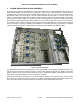

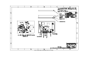

Table Of Contents
MXi501/1002U POWER AMPLIFIER HEATSINK ASSEMBLY
6 DIRECTIONAL COUPLER 21B2746G1
Drawing reference: Figure 12 and Figure 13
At the rear of the heatsink and fed by the output of the combiner is a directional coupler which is constructed from
edge coupled transmission lines. This is also a 4 port device similar to the 3dB couplers, except the coupling is
much weaker (-40dB nominal in this case). The input and output port of the directional coupler is the main output
50Ω transmission line, while the other two ports are the ends of the coupled line. The coupled line is simply a
second 50Ω transmission line laying parallel and spaced some distance away from the main line. The coupled
port closest to the amplifier output connector is terminated by a 51Ω resistor and the other coupled port is directly
connected to the centre pin of the ‘RF-TP’ (RF Test Point) BNC connector located on the rear panel of the
amplifier. The primary function of this directional coupler is to provide a low power RF sample of the forward
power appearing at the amplifier combined output. The nominal coupling is given as -40dB, but the coupling does
vary with frequency from about -43dB at 470MHz to about -38dB at 860MHz.
PUB11-014 Rev 1 July 2011 11-014-6 MXi501/1002U Power Amplifier Heatsink Assembly