
Specifications


41D2355 4-WAY SPLITTER UHF
PUB13-01 Rev 0 Mar 4, 2013 3
2 INPUTS AND OUTPUTS
The 4-Way Splitter requires DC Power, a Control and Monitoring Interface, an RF input drive and an output
connections to a higher power stages. Its inputs and outputs consist of the following:
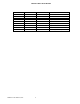
POWER IN: 2-Pin Connector J7
Pin Function
1
GND
2
+12VDC
AC receptacle 6EGG1-1 has built–in holder for slow blow 2A fuse model 218002.
MOD 1 IN and MOD 2 IN: SMA Connectors (50 ohm)
These are the RF signal inputs to the Splitter. Only one input is used to drive amplifiers at a time. These signals are
received from the Modulator #1 and Modulator #2(if used). If a matched 50-ohm attenuator pad has been installed
at the 4-Way Splitter Input, it must remain installed and must not be removed without first contacting LARCAN
Technical Service. The attenuator, when installed, protects the transmitter’s Power Amplifiers from being
overdriven.
SENSE 1 IN and SENSE 2 IN: SMA Connectors (50 ohm)
These are the RF signal from Mask Filter Input and Mask Filter Output respectively. These signals are switched to
SENSE 1 OUT 1 ans SENSE 2 OUT 1 when MOD 1 IN is selected. These signals are switched to SENSE 1 OUT 2
ans SENSE 2 OUT 2 when MOD 2 IN is selected. Only one input is used to drive amplifiers at a time. These
signals are received from the Modulator #1 and Modulator #2(if used). If a matched 50-ohm attenuator pad has
been installed at the 4-Way Splitter Input, it must remain installed and must not be removed without first contacting
LARCAN Technical Service. The attenuator, when installed, protects the transmitter’s Power Amplifiers from being
overdriven.
RF 1 OUT to RF 4 OUT: SMA Connector (50 ohm)
These are the four RF Outputs from the Splitter.
TELEMETRY: 9-Pin D-subminiature Connector.
Interface with Transmitter Control Unit is provided through this connector: Select Modulator 2 signal, FWD and RFL
telemetry, Aural and Reject 1,2 3 telemetry.
The Splitter can function as an amplifier gain block without the TELEMETRY interface connected to the transmitter’s
controller. This way bench testing of the RF circuits can be performed without connection to a transmitter controller.
The pinout of the Control and Monitoring interface is as follows.