
Specifications


41D2355 4-WAY SPLITTER UHF
PUB13-01 Rev 0 Mar 4, 2013 8
5 ANALOG INTERNALLY DIPLEXED FWD, RFL AND AURAL RF DETECTORS
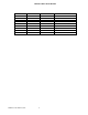
Jumpers JP1, JP2, JP3 and JP4 in A position.
RF Power levels throughout the transmitter are sampled in directional couplers and the resulting RF samples are
detected and appropriately processed to provide DC outputs corresponding to the amplitude of the desired
parameter of the input signal. These DC outputs contribute to the AGC/VSWR supervision of the transmitter and are
also processed in analog to digital conversion circuits on the various controller boards to provide digital metering.
NTSC and PAL application differ only in their color subcarrier frequency, consequently in a few component values.
Required signal levels are as follows:
• FWD (overall forward sample) metering requires 23dBm sync peak signal for full scale (100% rated power)
• RFL (overall reflected sample) metering requires 13dBm sync peak signal for full scale (10% rated power)
The RF detectors are used for internally diplexed transmitters to measure:
• forward visual signal and forward aural signal at port J18
• reflected combined visual and aural signal at port J19
The module provides DC outputs corresponding to the instantaneous forward and reflected RF levels at the back
porch (blanking level) of the modulated signal, so that output remains proportionally constant regardless of video
signals to the transmitter. Two almost identical detector circuits reside on a single board for visual forward and
reflected metering. Detection sensitivity of the circuit dedicated to reflected visual power is approximately 10dB
greater than for the visual forward RF detector circuit. The aural metering circuit takes a sample of detected video
signal from the forward port and provides DC level proportional to the amplitude of the aural carrier. The sample of
this DC level is used to compensate visual forward reading affected by presence of the aural carrier at the forward
port. The reflected port does not have this compensation circuit, so in reality the reflected reading is combined
visual and aural power.
5.1 CIRCUIT DESCRIPTION
The board is fitted with two RF detectors, which respond to RF samples fed from RF directional couplers mounted on
transmission lines in the Amplifier Cabinets and on external probe sections. The modulation envelope blanking level is
measured because it remains constant, regardless of the picture content of the transmission. Measurement occurs
during the back porch. Both sections of the board are configured in a similar way.
5.1.1 J18 Channel – Visual Forward
The RF sample is applied to input J18 and is terminated by R557IIR522. CR501 and Q505 form an envelope
detector. CR501 is forward biased slightly by R514 and R521 to overcome CR501 conduction threshold voltage,
thereby improving detection linearity. Q505 is forward biased by R521 as well, and when RF is applied, Q505 is
driven in the direction of turn off during each positive-going half cycle, thus causing its emitter voltage to become
more positive, and in effect forming a linear envelope detector.
C546 utilizes the lead inductances of CR501 and Q505 to form a TEE network, which provides a matching section
that improves the UHF signal transfer between the devices. Q505 and CR501 have similar temperature coefficients
and the opposing connection of the two in this back-to-back configuration provides temperature compensation.