
User's Manual


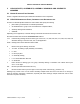


Table Of Contents
- 1 MXi201V AMPLIFIER–INTRODUCTION
- 2 SAFETY NOTICES
- 2.1 Beryllium Oxide Warning
- 2.2 Other Toxic Materials
- 2.3 Dangerous Voltages
- 3 LARCAN PARTS, ASSEMBLIES, ASSEMBLY DRAWINGS AND SCHEMATIC NUMBERS
- 1 MXi CONTROLLER
- 2 AMPLIFIER INSTALLATION AND STARTUP
- 3 TEST AND TROUBLESHOOTING
- 4 MAINTENANCE
- 5 SERVICE
- 6 TEST EQUIPMENT SETUP
- 7 SPECIFICATIONS
- 1 MXi DUAL PALLET VHF AMPLIFIER
- 1 FUNCTIONAL DESCRIPTION:
- 2 RF PREAMPLIFIER
- 3 POWER AMPLIFIER:
- 4 TWO-WAY SPLITTER/COMBINER
- 5 ADJUSTMENT OF BIAS VOLTAGE TO ESTABLISH PROPER QUIESCENT FET BIAS CURRENT:
- 6 LOW POWER SWEEP AMPLIFIERS
- 1 MXi POWER SUPPLY LAR1000-50-P5337
- 2 POWER SUPPLY DATA SHEET REPRINT

MXi201V TECHNICAL SERVICE MANUAL
1 MXi201V AMPLIFIER–INTRODUCTION
This Technical Service Manual contains publications (PUBs) describing the technical details of the MXi201V
amplifier, as well as the overall operating instructions, including the bench test procedures of the amplifier stages
incorporated in this unit. It also covers the transmitter’s start-up operation, and troubleshooting, as well as basic
transmitter maintenance guidelines.
The RF section of the MXi201V Amplifier consists of a heatsink assembly that includes five cascaded broadband
amplifier modules and a splitter and combiner and a directional coupler.
Figure 1 shows the layout of this
assembly.
Figure 1 MXi Amplifier Heatsink Assembly
Also mounted on the heatsink is a thermal switch that protects the amplifier from over temperature conditions.
TSM21Q-365 Rev 0 July 17, 2009 MXi201V 3