
User Manual


Unit 2 – IF Modulator
- 20 -
9. Power Supply (optional):
9.1. Function:
The switched power supply has the function to generate +12V and -12V voltages from the input
voltages AC or from the +36V battery (opc).
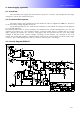
9.2. Technical Description:
The input voltage, after transformer T2 and diodes D1 and D4, supplies the PWM IC1. If there is
no AC the battery voltage supplies the circuit.
The pulses generated by IC1 commute the transistor Q1 and switch the voltage over the primary
T1 at 25 KHz frequency.
The induced pulses that are in the secondary are rectified by D7 and D8 and filtered by C8 e C9. The
regulator IC2 assures the -12V regulated voltage. A voltage sample after L1 supplies the IC1 control
input, through the divider R11 and R12. The pulses that are generated for IC1 have their width
changed in function of the received sample, canceling, in this manner, any variation in the +12V
voltage. The resistor R9 supplies a sampled voltage related to the current which circulates in the output
to the IC1, pin 3. This input protects the over current, reducing the +12V voltage.
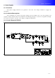
9.3. Circuit diagram FTE017: