
User's Manual Part 2
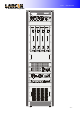
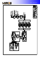
Table Of Contents

Unit 1 – Introduction
- 3 -
Unit IV UHF 50W Amplifier
1. UHF 50W Amplifier: Page 02
2. Frontal and Back Panel: Page 03
3. Switched Power Supply +32V 14 A: Page 05
4. 50W UHF Amplifier Protections: Page 10
5. Power Detecting and Power Limiting Protection: Page 14
6. 2W UHF Amplifier: Page 16
7. 50W Output Amplifier: Page 19
8. 50W UHF Amplifier Circuit Diagram Page 23
Unit V 625W Amplifier
1. 625W Amplifier: Page 02
2. Frontal and Back Panel: Page 03
3. +32V 25 A Switched Power Supply: Page 05
4. 625W Amplifier Protections: Page 09
5. Output Supply: Page 13
6. 625W Final Amplifier: Page 15
7. 625W UHF Amplifier: Page 19
Unit VI cabling e attributes
1. Protection and Command: Page 02
2. Transient Suppressor main AC: Page 07
3. Temperature Sensor: Page 09
4. TV Monitor: Page 11
5. Meter Panel: Page 16
6. Remote monitoring: Page 20
7. Notch Filter: Page 23
8. Command and Protection Board: Page 26
9. Rack Cabling: Page 27