
User's Manual Part 2

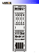
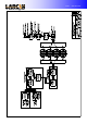
Table Of Contents

Unit 1 – Introduction
- 8 -
2.3. Amplifier Levels:
2.3.1. Comment/Composition/Origin:
The T2500U is composed for 4 625W amplifier modules combined through 3dB hybrid couplers.
The final modules are drived by a 50W amplifier and 3 dB hibrid couplers as splitters.
All the amplifiers are in solid state.
2.3.2. Protections/Signaling:
Each 625W amplifier has a VSWR protection, temperature and a power limiting circuit.
The output power, VSWR, temperature, current and module voltage can be monitored through a
DB9 connector in the front panel.
In the frontal panel there are the normal power indication (Green Led), low power (red led) and
excessive VSWR (red led). There is, also, a BNC connector for monitoring the output signal of each
module.
At the transmitter output, there is the video and audio power monitoring, antenna VSWR, power
supply antenna, current and voltage and indications of excessive VSWR, excessive filter VSWR, power
supply temperature alarm, video absence, phase fail and others.
There is at the transmitter top, a DB25 connector with transmitter signals, for remote
monitoring.
2.4. Notch filter:
It is used to attenuate out channel spurious generated by the transmitter. It is composed by 11
cavities, 10 are syntonized in the spurious frequencies and 1 in the 2
nd
harmonic.