
Installation Manual

Larson Electronics LLC www.Magnalight.com
9419 E US HWY 175, Kemp, TX 75143 - P: (800) 369-6671 - F: (903) 498-3364 - E: sales@magnalight.com
INSTRUCTIONS FOR WIRING LAMP
Remove the upper center screw cap on the re-lamp end (field wiring compartment).
Install approved cable connector or conduit fitting into ½" npt hub on field wiring
compartment.
Install a three conductor cable into the connector, allowing 3 inches of wire inside
compartment for connection.
Using approved wire connectors, splice wires as per color codes: black to black (line) white
to white (common) and green to green (ground).
Replace end-cap, making sure there are no wires protruding that may be pinched causing a
possible short circuit.
WARNING: Fixture must be grounded as required per paragraph 410-21 and article 250 of the
National Electric Code and/or rule 30-500. Failure to properly ground this fixture will create an electrical
shock, which can cause serious injury or death.
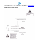
EMERGENCY BACKUP BALLAST OPERATION
During normal operation, AC power is supplied to the ballast through the backup micro inverter and the
inverter charges the battery. Connecting the inverter wires (red and white) enables the emergency
circuit and supplies power to the control/monitor circuit. The backup micro inverter detects AC input
voltage (120-277V AC) and automatically set the output voltage during emergency operation.
When AC power fails, the backup micro inverter automatically switches to emergency mode, keeping
the load illuminated for a minimum of 90 minutes. When AC power is restored, the backup micro
inverter returns to charge mode to recharge the battery.
The backup micro inverter consists of a low-battery voltage disconnect which is reset when AC power is
restored. The unit can also detect an abnormal load condition (open or shorted load) during emergency
mode operation and will protect the inverter from damage.