
Installation Guide
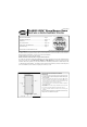


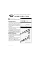


202220565 CLASSIC-VIEW SERIES
5
FIGURE 18
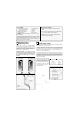
Install Latch Side Z-Bar
(FOR STANDARD SIZE MODELS WITH MORTISE HARDWARE.)
NOTE: Surface mount models do not have slots routed in the
door frame for hardware.
Measure and cut latch side z-bar using same method as outlined in
step 4. Position the latch z-bar (sliding it left or right) to allow 1/8" gap
between door and latch side z-bar. Fasten using #8x1" painted
panhead screws (Figure 17).
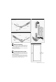
Install Latch Side Z-Bar
(FOR MODELS WITH SURFACE-MOUNT HARDWARE.)
10a
FIGURE 17
NOTE: you will only use (1 of 2) latch side instructions
in step 10 depending on your door model.
Top: Determine which end of the Z-bar is top and mark it with a piece
of tape.
Bottom Cut: Measure down from the underside of the installed drip
cap (Figure 16) to the top of the door threshold. Using this
measurement, measure down from the top of the Z-bar. Cut the Z-bar
to match the slope of the sill. (Refer to steps 3 and 4). Mark a line
around the bottom. Cut the Z-bar to length (Figure 18).
Set the Z-bar in place between the door and the wood jamb. Allow a
3/16" gap between the door and the latch-side Z-bar. Using #8x1"
painted pan head screws, attach the latch-side Z-bar to the wood jamb
using the Z-barʼs pre-drilled holes as a guide. Do not over-tighten
screws.
Refer to separate instructions packaged in the hardware box.
*CAUTION: Be sure to install storm door hardware at a height that
will not interfere with the prime door hardware.
*Retain the parts list for future reference.
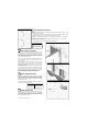
Install Latch and Strike Hardware
9
10b
FIGURE 19
Although not always necessary, you can apply caulking behind the
Z-bars (latch, hinge, and top), or along front edge of Z-bar (Figures
12 & 16).
Seal Frame with Caulking
(optional)
11
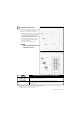
Adjust the Bottom Expander
12
Adjust the bottom expander so that the vinyl sweeps touch the
door threshold. The slotted holes in the expander should be
located on the inside of the door. Centrally locate the two #6x3/8"
pan head screws (Figure 19) in the slot to allow for future
adjustments.
Drill 3/32" diameter pilot holes for the screws, being careful not to
drill all the way through to the front face of the door.