
Installation Guide

PAGE 8
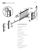
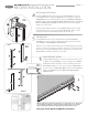
SIDE VIEW
HEAD
OPENING HEIGHT
OUTSIDE
A
K
N
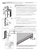
MOUNTING THE SCREEN CASSETTE
Slide the K-Surface Mount ‘L’ Clips into the top of the A-Screen Cassette.
The clips should be evenly spaced along the A-Screen Cassette Assembly.
Make sure cassette is level and then screw clips in place with N-#8x1” (25mm)
Pan Head Screws.
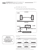
3
2
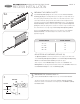
OPENING WIDTH
36”- 72”
73”-120”
120”-140”
140”-192”
SPRING TENSION
25
30
35
40
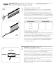
3
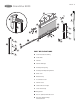
OPPOSITE END OF CARTRIDGE (SEE PAGE 10)
Test Operating Wand for smooth operation. If it’s too tight, loosen allen screw
on the F-End Cap with Operating Wand. Insert the F-End Cap with Operating
Wand into A-Screen Cassette Assembly and push into place.
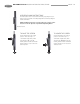
Slide one piece of the H-Weatherstrip into bottom slot of C-Pull Bar. The
M-Weight Bars are already inserted inside the hollow of the C-Pull Bar. Now insert
the D-Pull Bar End Caps into ends of C-Pull Bar [Fig 2B].
C
A
H
D
D
M
E
A
H
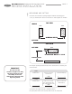
2A
2B
PREPARING THE SCREEN CASSETTE
Insert E-End Cap with Spring into the correct end of the A-Screen Cassette
Assembly [Fig 2A] (the assembly will only fit correctly in one end). Make sure to
line up the spring and bushing notches with one of the small slots in the center
screen tube. Wind the spring clockwise the number of turns designated in the
following chart and push the E-End Cap with Spring in place on the A-Screen
Cassette Assembly. A rubber mallet is helpful to fully seat the E-End Cap with
Spring. Note that the spring in the cassette is for tension only. You will need to
raise and lower the screen by using the F-End Cap with Operating Wand.
Remove the H-Weatherstrip from the groove at the back of the A-Screen
Cassette Assembly. This weatherstrip is not used in a surface mount
application [Fig 2A].
GRANDVUE 800 INSTALLATION INSTRUCTIONS
RECESS INSTALLATION