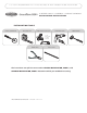
I T I S H I G H LY R E C O M M E N D E D T H A T T H E I N S T R U C T I O N S B E R E A D T H R O U G H B E F O R E I N S T A L L A T I O N . GrandVue E800 S C R E E N E D P OR C H • GA Z E B OS • GA R A GE O P E N I N G S I N S TA L L AT I O N I N S T R UC T I O N S INSTALLATION TOOLS PHILLIPS SCREWDRIVER MEASURING TAPE HAND-HELD OR POWER SAW POWER DRILL & BITS RUBBER MALLET Use saw blade suitable for cutting aluminum.
PA G E 2 GrandVue E800 I F H J N G I J E A N B F D N K O B O N N M J E N C N N B PART DESIGNATIONS L A Screen Cassette Assembly B Inside Rails C Outside Rails D Pull Bar E Pull Bar End Caps F End Cap with Spring G End Cap with Operating Wand H Chain Lock I Recess Mount Clips J Weatherstrip K Foot Release Lever L Pull Bar Locks M Weight Bar N #8 x 1” (25mm) Panhead Screw O #6 x 3/8” (9mm) Phillips Panhead Screw L C
G R A N D V U E 8 0 0 I N S TA L L AT I O N I N S T R U C T I O N S PA G E 3 RECESS INSTALLATION 1 MEASURING AND CUTTING Determine the maximum opening height & width for mounting your screen, as shown below. Check for interference with any door or window.
G R A N D V U E 8 0 0 I N S TA L L AT I O N I N S T R U C T I O N S PA G E 4 RECESS INSTALLATION 2 2A PREPARING THE SCREEN CASSETTE Insert F-End Cap with Spring into the correct end of the A-Screen Cassette Assembly [Fig 2A] (the assembly will only fit correctly in one end). Make sure to line up the spring and bushing notches with one of the small slots in the center screen tube.
G R A N D V U E 8 0 0 I N S TA L L AT I O N I N S T R U C T I O N S PA G E 5 RECESS INSTALLATION 4 4A E INSTALLING SIDE RAILS Install the L-Pull Bar Locks at the bottom of each B-Inside Rail. Be sure that the L-Pull Bar Locks can engage the D-Pull Bar as shown [Fig 4C]. Slide both C-Outside Rails onto the tabs protruding from the F and G-Cassette End Caps [Fig 4A]. Attach to jamb with N-#8x1” (25mm) Panhead Screws.
PA G E 6 GrandVue E800 K N N N E N D N B L E N M L L O O H D L J N B C N I N F H A B N G N PART DESIGNATIONS A Screen Cassette Assembly B Inside Rails C Pull Bar D Pull Bar End Caps E End Cap with Spring F End Cap with Operating Wand G Chain Lock H Weatherstrip I Foot Release Lever J Pull Bar Locks K Surface Mount ‘L’ Clips L Screw Cover Caps M Weight Bar N #8 x 1” (25mm) Panhead Screw O #6 x 3/8” (9mm) Phillips Panhead Screw N L N L J
G R A N D V U E 8 0 0 I N S TA L L AT I O N I N S T R U C T I O N S PA G E 7 RECESS INSTALLATION 1 MEASURING AND CUTTING Determine the maximum opening height & width for mounting your screen, as shown below. Check for interference with any door or window. TOP VIEW INSIDE JAMB JAMB OPENING WIDTH OUTSIDE SIDE VIEW OUTSIDE HEAD K-SURFACE MOUNT ‘L’ CLIP OPENING HEIGHT SILL or FLOOR Record your opening measurements on the chart below to calculate your IMPORTANT Be sure to make smooth, straight cuts.
G R A N D V U E 8 0 0 I N S TA L L AT I O N I N S T R U C T I O N S PA G E 8 RECESS INSTALLATION 2A 2 H PREPARING THE SCREEN CASSETTE Insert E-End Cap with Spring into the correct end of the A-Screen Cassette Assembly [Fig 2A] (the assembly will only fit correctly in one end). Make sure to line up the spring and bushing notches with one of the small slots in the center screen tube.
G R A N D V U E 8 0 0 I N S TA L L AT I O N I N S T R U C T I O N S PA G E 9 RECESS INSTALLATION 4A 4 E Install the J-Pull Bar Locks at the bottom of each B-Inside Rail. Be sure that the J-Pull Bar Lock can engage the C-Pull Bar as shown in image [Fig 4C]. Slide B-Inside Rails onto the tabs protruding from the E and F-Cassette End Caps, with the shorter pile to the inside [Fig 4D]. Use an 1/8” drill bit and first drill through both sides of the B-Inside Rails where they are to be fastened.
G R A N D V U E 8 0 0 I N S TA L L AT I O N I N S T R U C T I O N S PA G E 1 0 OPERATING WAND INSTRUCTIONS The Retractable Screen is raised and lowered by squeezing the top or bottom of the tilt handle on the Operating Wand and then pulling the handle downward. NOTE: DO NOT operate the screen by pulling up or down on the bottom screen rail. Operate only with the Operating Wand. Neutral Position 1 2 TO RAISE THE SCREEN TO LOWER THE SCREEN Put the tilt handle in the neutral position.
G R A N D V U E 8 0 0 I N S TA L L AT I O N I N S T R U C T I O N S PA G E 1 1 TROUBLESHOOTING GUIDE Retractable screens should always be installed square, plumb and level. THE SCREEN FABRIC GETS BLOWN OUT OF THE SIDE TRACKS Shorter Pile An Anti-Wind Brush Pile is located inside the Inside Rails. This Anti-Wind Pile is designed so that the stiff bristles of the Brush Pile will engage inside the holes of the screen fabric as wind blows/pushes on the fabric.
GrandVue 800 WARRANTY PA GE 1 2 Retractable Screen Warranty Larson Manufacturing Company Retractable Screen Limited Five Year Warranty The five year limited warranty applies to the original purchaser of owner occupied homes and covers mechanical components excluding screen fabrics. LARSON warrants the cassette, mounting rails and latch to be free from defects in manufacturing, materials, paint adhesion or workmanship, under normal use, for the period stated above.